Method for inhibiting occurrence of pyrolysis deposit in pyrolysis gasification system, and pyrolysis gasification system

a gasification system and pyrolysis technology, applied in the direction of lighting and heating apparatus, combustion types, incinerator apparatus, etc., can solve the problems of increasing fan output and vibration in association with impeller balance deterioration, and achieve the effect of inhibiting the occurrence of pyrolysis deposits, increasing fan output and vibration, and preventing deterioration of impeller balan

Active Publication Date: 2019-08-13
MITSUBISHI HEAVY IND ENVIRONMENTAL & CHEM ENG CO LTD
View PDF24 Cites 0 Cited by
  • Summary
  • Abstract
  • Description
  • Claims
  • Application Information

AI Technical Summary

Benefits of technology

[0029]In the method for inhibiting the occurrence of a pyrolysis deposit in a pyrolysis gasification system and the pyrolysis gasification system described above, when the oxygen-containing gas is fed to the pyrolysis gas separated from the carbide in the solid-gas separation unit while the pyrolysis gasification system is operating, it is possible to produce a high-temperature flame by the oxygen in the oxygen-containing gas, and burn and decompose pyrolysis components, such as tar, in the pyrolysis gas by this flame. Accordingly, it is possible to inhibit the occurrence of a pyrolysis deposit in a pyrolysis gas line for introducing the pyrolysis gas to the combustion furnace.
[0030]Thus, according to the method for inhibiting the occurrence of a pyrolysis deposit in a pyrolysis gasification system and the pyrolysis gasification system described above, it is possible to inhibit the occurrence of a pyrolysis deposit itself during continuous operation without stopping facilities. Then, because it is thus possible to inhibit the occurrence of a pyrolysis deposit, the occurrence of, for example, blockage of the pipe, and an increase in fan output and vibration in association with deterioration in impeller balance can be prevented, making it possible to significantly decrease maintenance frequency and operate the pyrolysis gasification system with high efficiency.

Problems solved by technology

Then, when the amount of the adhered and accumulated pyrolysis deposit increases as a result of continuous operation, for example, blockage of the pipe, and an increase in fan output and vibration in association with deterioration of impeller balance occur.

Method used


Image

  • Method for inhibiting occurrence of pyrolysis deposit in pyrolysis gasification system, and pyrolysis gasification system
  • Method for inhibiting occurrence of pyrolysis deposit in pyrolysis gasification system, and pyrolysis gasification system
  • Method for inhibiting occurrence of pyrolysis deposit in pyrolysis gasification system, and pyrolysis gasification system

Examples


Embodiment Construction

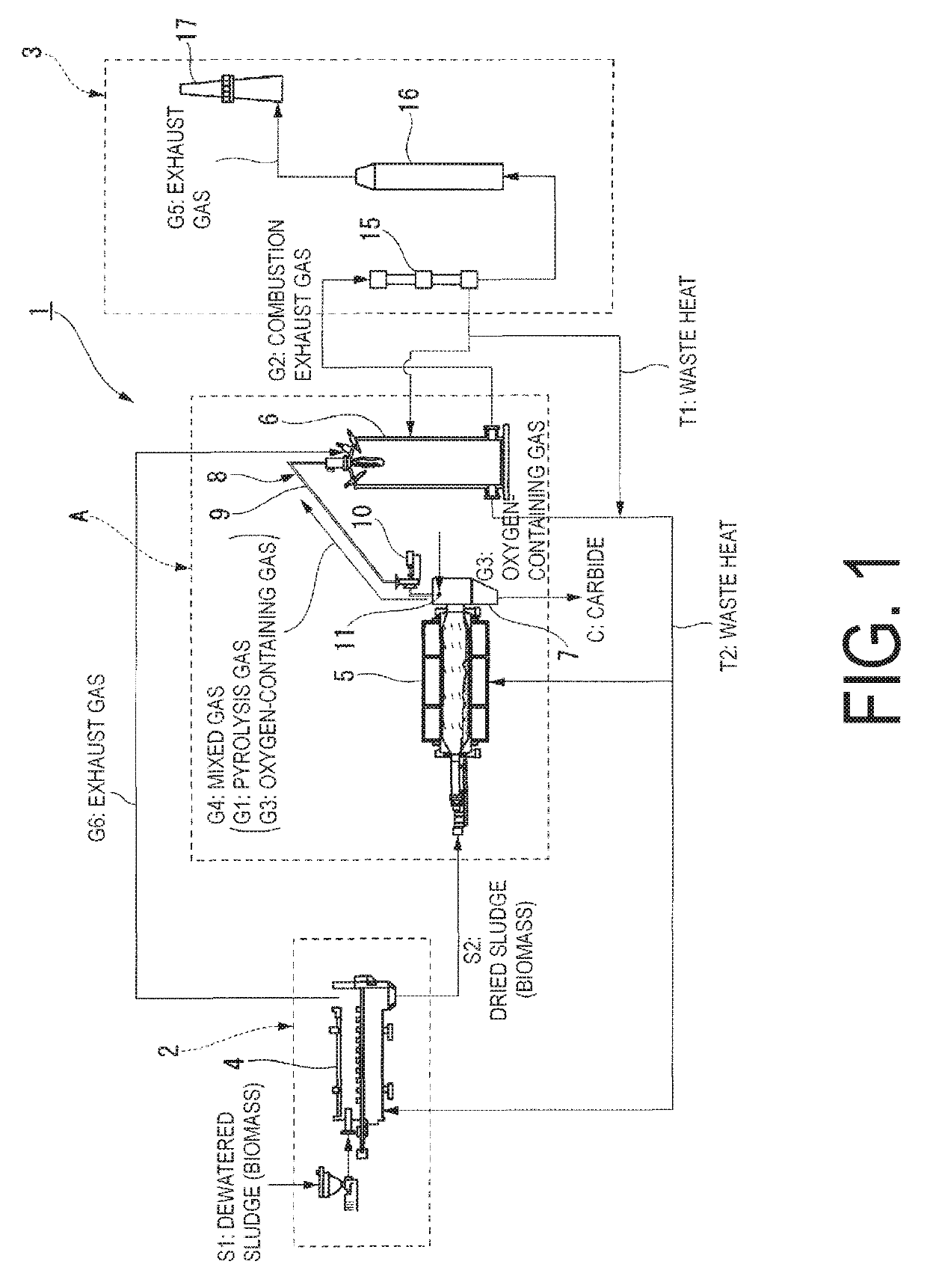
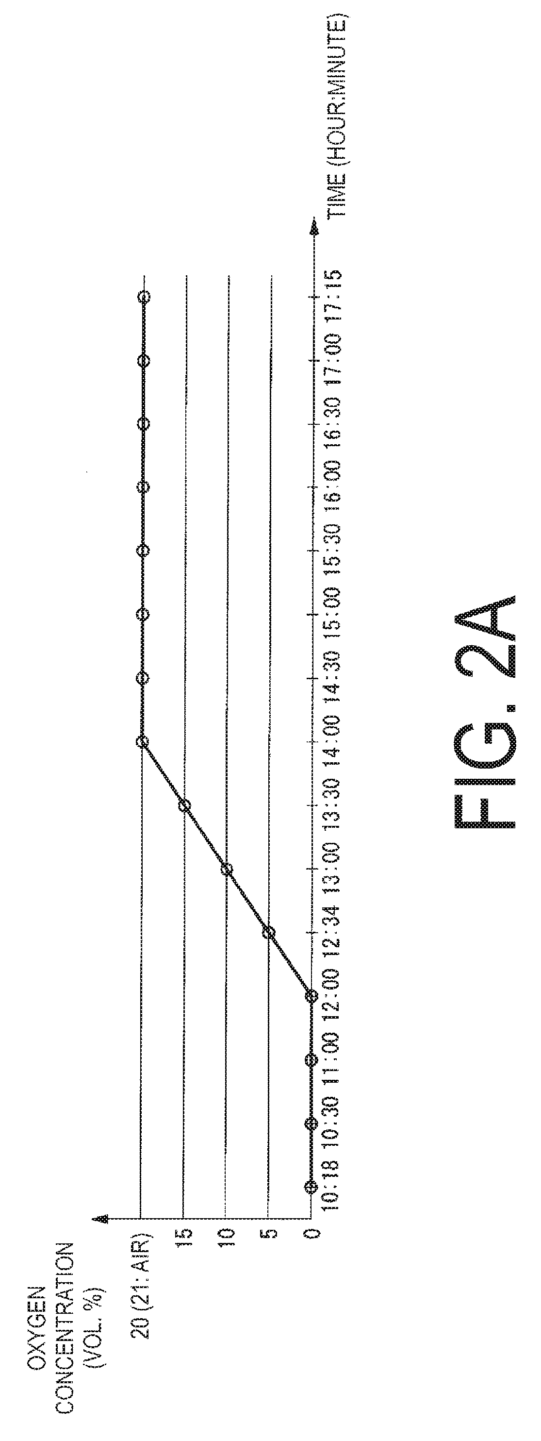
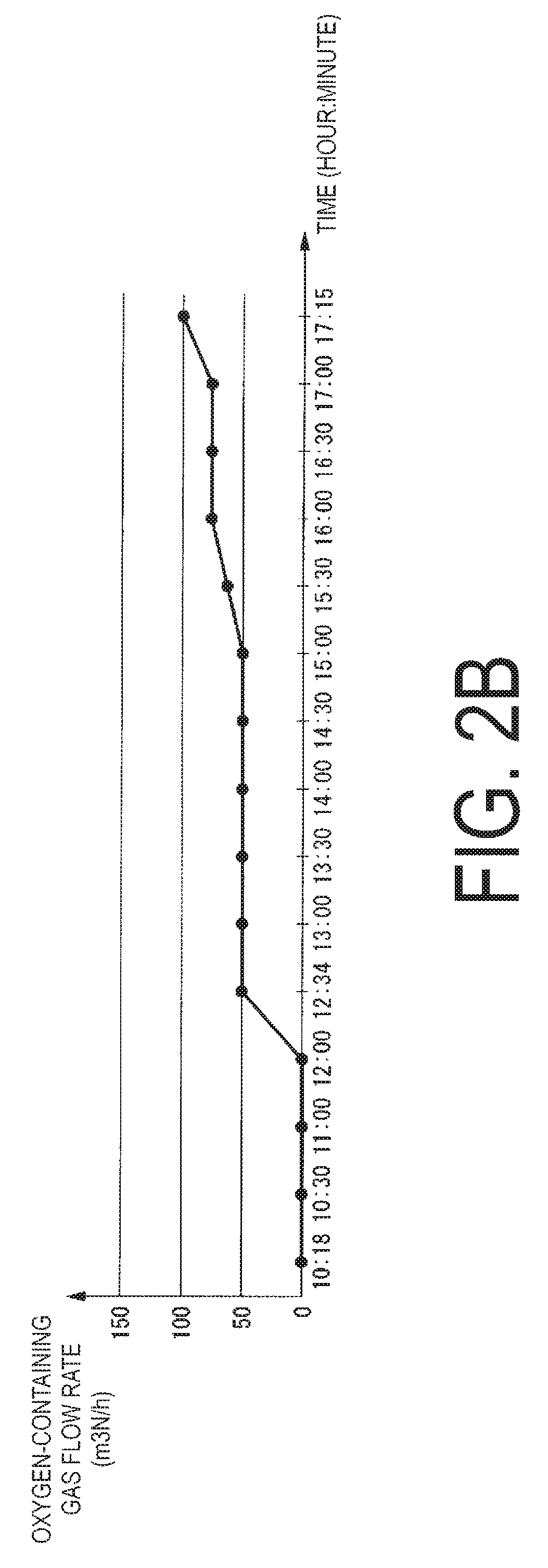
[0035]The following describes a method for inhibiting the occurrence of a pyrolysis deposit in a pyrolysis gasification system and a pyrolysis gasification system according to an embodiment of the present invention, with reference to FIG. 1 and FIGS. 2A to 2C. Here, in the present embodiment, the pyrolysis gasification system according to the present invention is described as a pyrolysis gasification facility of a carbonization system that manufactures carbonized fuel (carbide) for power generation from a sewage sludge. It should be noted that the present invention is of course not limited to a pyrolysis gasification system for gasifying a sewage sludge, and is applicable to various pyrolysis gasification systems, such as a pyrolysis gasification system for gasifying other biomass such as a woody biomass.

[0036]A carbonization system 1 of the present embodiment is configured to include a drying process facility 2 that subjects a sewage sludge (a dewatered sludge, a biomass) S1 to a d...


PUM

PropertyMeasurementUnit
temperatureaaaaaaaaaa

Abstract

This method for inhibiting the occurrence of a pyrolysis deposit in a pyrolysis gasification system includes: gasifying biomass (S2) through pyrolysis in a pyrolysis gasification furnace (5); separating, in a solid-gas separation unit (7), a pyrolysis gas (G1) and a carbide (C) continuously formed through pyrolysis of the biomass (S2); feeding an oxygen-containing gas (G3) to the separated pyrolysis gas (G1); and introducing the pyrolysis gas (G1) together with the oxygen-containing gas (G3) to a combustion furnace (6) through a pipe (9) which constitutes a pyrolysis gas line (8).

Description

RELATED APPLICATIONS[0001]The present application is National Phase of International Application No. PCT / JP2013 / 068984 filed Jul. 11, 2013 the disclosure of which is hereby incorporated by reference herein in its entirety.TECHNICAL FIELD[0002]The present invention relates to a method for inhibiting the occurrence of a pyrolysis deposit in a pyrolysis gasification system that gasifies a biomass, such as a sewage sludge or a woody biomass, and a pyrolysis gasification system therefor.BACKGROUND ART[0003]The gasification of a biomass, such as a sewage sludge or a woody biomass, in a pyrolysis gasification system and conversion of the biomass, which has been conventionally treated as waste, into resources for effective use has been in demand. For example, manufacturing a carbide by gasifying and carbonizing a sewage sludge in a pyrolysis gasification system, and using the carbide as carbonized fuel for power generation has been proposed and put to practical use.[0004]Examples of carboni...

Claims


Application Information

Patent Timeline
Patent Type & Authority Patents(United States)
IPC IPC(8): C10B27/06F23G7/10C10B53/02F23L7/00F23G5/027C10B47/28C10B47/30
CPCC10B27/06C10B47/28C10B53/02F23G5/0276F23G7/10F23L7/007Y02P20/145C10B47/30F23G2201/303F23G2207/30Y02E20/344Y02E50/14Y02E20/34Y02E50/10
Inventor ENDOU, YUUKIKITTA, TAKEHIROKAKURATA, KAZUAKIABE, JUNICHIRO
Owner MITSUBISHI HEAVY IND ENVIRONMENTAL & CHEM ENG CO LTD
Why Eureka
Try Eureka