
Display panel and method of testing the same

a display panel and display device technology, applied in the direction of instruments, static indicating devices, etc., can solve the problems of panel shrinkage, panel failure, panel drive failure, etc., and achieve the effect of reducing or minimizing the changes in the structure and/or manufacturing process of the display panel and easy detection of internal cracks

Active Publication Date: 2019-07-30
SAMSUNG DISPLAY CO LTD
View PDF27 Cites 1 Cited by
  • Summary
  • Abstract
  • Description
  • Claims
  • Application Information

AI Technical Summary

Benefits of technology

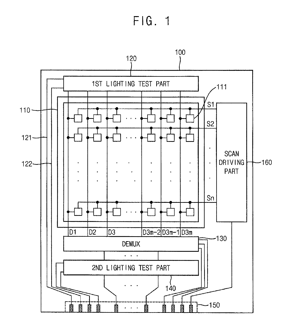
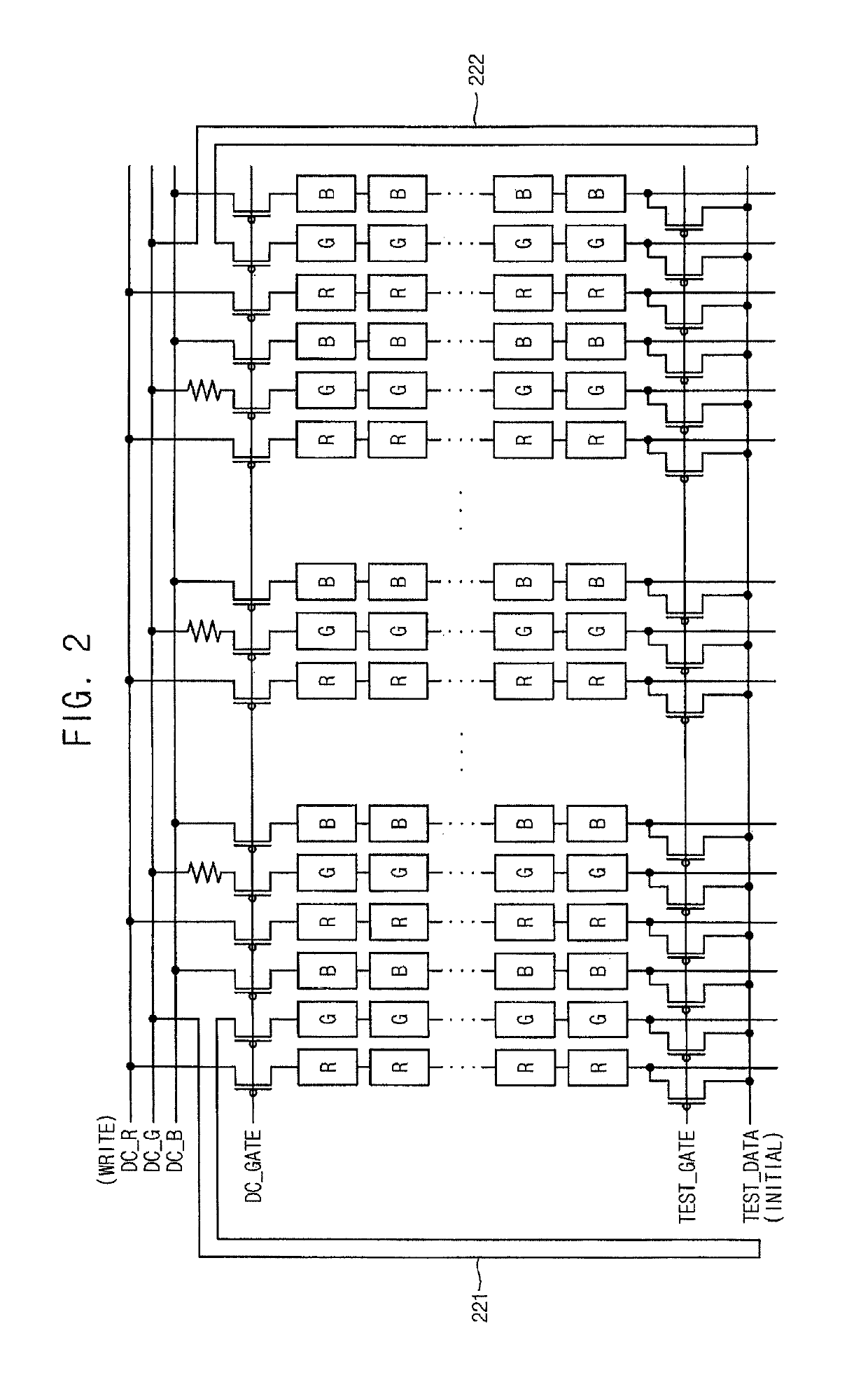
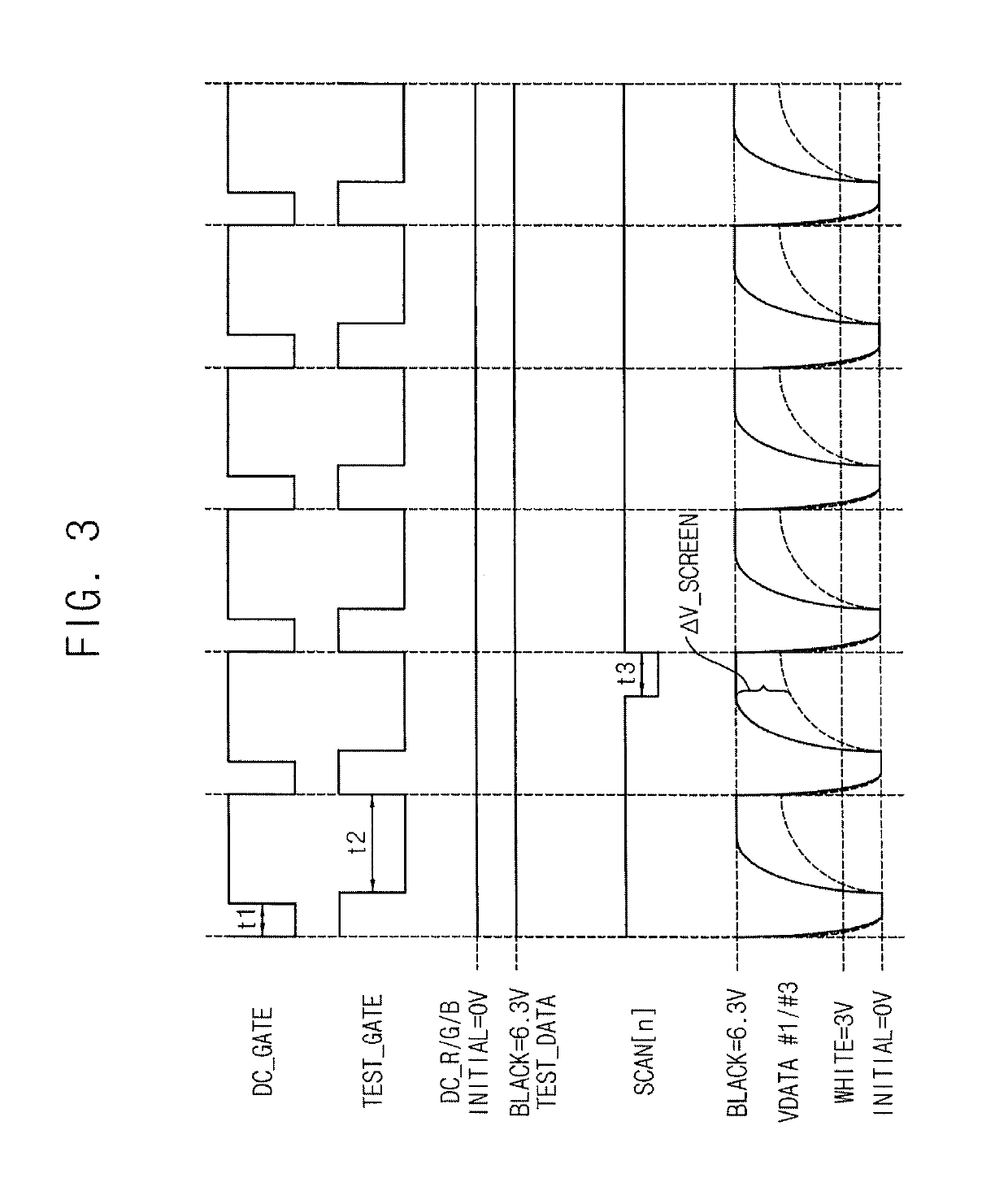
[0032]Therefore, a display panel according to example embodiments may relatively easily detect internal cracks of the display panel while changes in the structure and / or process of manufacturing the display panel are minimized or reduced by including a lighting test line arranged in an outer area of the display panel, where a lighting state of the display panel is changed in response to a resistance variation of the lighting test line.

Problems solved by technology

During manufacturing, cracks (or, defects) may occur in various components, wiring, and the substrate during a manufacturing process steps such as an etching process, a cutting process, etc.
The cracks may result in problems such as panel driving failures, panel shrinkages, etc.
For example, in the case of a foldable display panel or a rollable display panel, severe cracks due to external forces may occur (or, appear) as the display panel is folded / unfolded or rolled / unrolled.
However, the lighting test has limits to detect micro-cracks.
In addition, the lighting test may be carried out before a driving integrated circuit is mounted in a display panel, so that the lighting test may not detect cracks that occur after the driving integrated circuit is mounted in the display panel.

Method used


Image

  • Display panel and method of testing the same
  • Display panel and method of testing the same
  • Display panel and method of testing the same

Examples


Embodiment Construction

[0045]Hereinafter, aspects of example embodiments of the present invention will be explained in more detail with reference to the accompanying drawings, in which like reference numbers refer to like elements throughout. The present invention, however, may be embodied in various different forms, and should not be construed as being limited to only the illustrated embodiments herein. Rather, these embodiments are provided as examples so that this disclosure will be thorough and complete, and will fully convey the aspects and features of the present invention to those skilled in the art. Accordingly, processes, elements, and techniques that are not necessary to those having ordinary skill in the art for a complete understanding of the aspects and features of the present invention may not be described. Unless otherwise noted, like reference numerals denote like elements throughout the attached drawings and the written description, and thus, descriptions thereof will not be repeated. In ...


PUM


Abstract

A display panel includes: a display including pixel columns electrically connected to data lines; a non-display area adjacent the display; a test circuit configured to receive a lighting test signal passing through at least a portion of the non-display area and to transfer the lighting test signal to the data lines in response to a test control signal; and a switch configured to receive a data signal from an external component and to transfer the data signal to the data lines in response to a switching signal.

Description

CROSS-REFERENCE TO RELATED APPLICATION[0001]This application claims priority to and the benefit of Korean Patent Application No. 10-2015-0030282, filed on Mar. 4, 2015 in the Korean Intellectual Property Office (KIPO), the content of which is incorporated by reference herein in its entirety.BACKGROUND[0002]1. Field[0003]Example embodiments of the present invention relate to a display device and / or a display panel and a method of testing the same.[0004]2. Description of the Related Art[0005]Generally, organic light emitting display devices include a display panel that displays an image, a scan driver that provides a scan signal to the display panel, a data driver that provides a data signal to the display panel, and an emission control driver that provides an emission control signal to the display panel.[0006]Display panels are generally manufactured through a sophisticated semiconductor manufacturing process. During manufacturing, cracks (or, defects) may occur in various components...

Claims


Application Information

Patent Timeline
Patent Type & Authority Patents(United States)
IPC IPC(8): G09G3/00G09G3/3291
CPCG09G3/006G09G3/3291G09G2310/0297G09G2310/0291G09G2300/0426G09G3/3208
Inventor KWAK, WON-KYUJANG, HWAN-SOOLEE, SEUNG-KYU
Owner SAMSUNG DISPLAY CO LTD
Learn More