
Sealed and thermally insulated tank fitted with a through-element

a technology of through-element and seal, which is applied in the field of seals and thermal insulation tanks, can solve the problems of increasing the complexity of the network of corrugated in this way, and the possibility of similar problems in the top wall of the tank

Active Publication Date: 2019-07-30
GAZTRANSPORT & TECHNIGAZ
View PDF16 Cites 0 Cited by
  • Summary
  • Abstract
  • Description
  • Claims
  • Application Information

AI Technical Summary

Benefits of technology

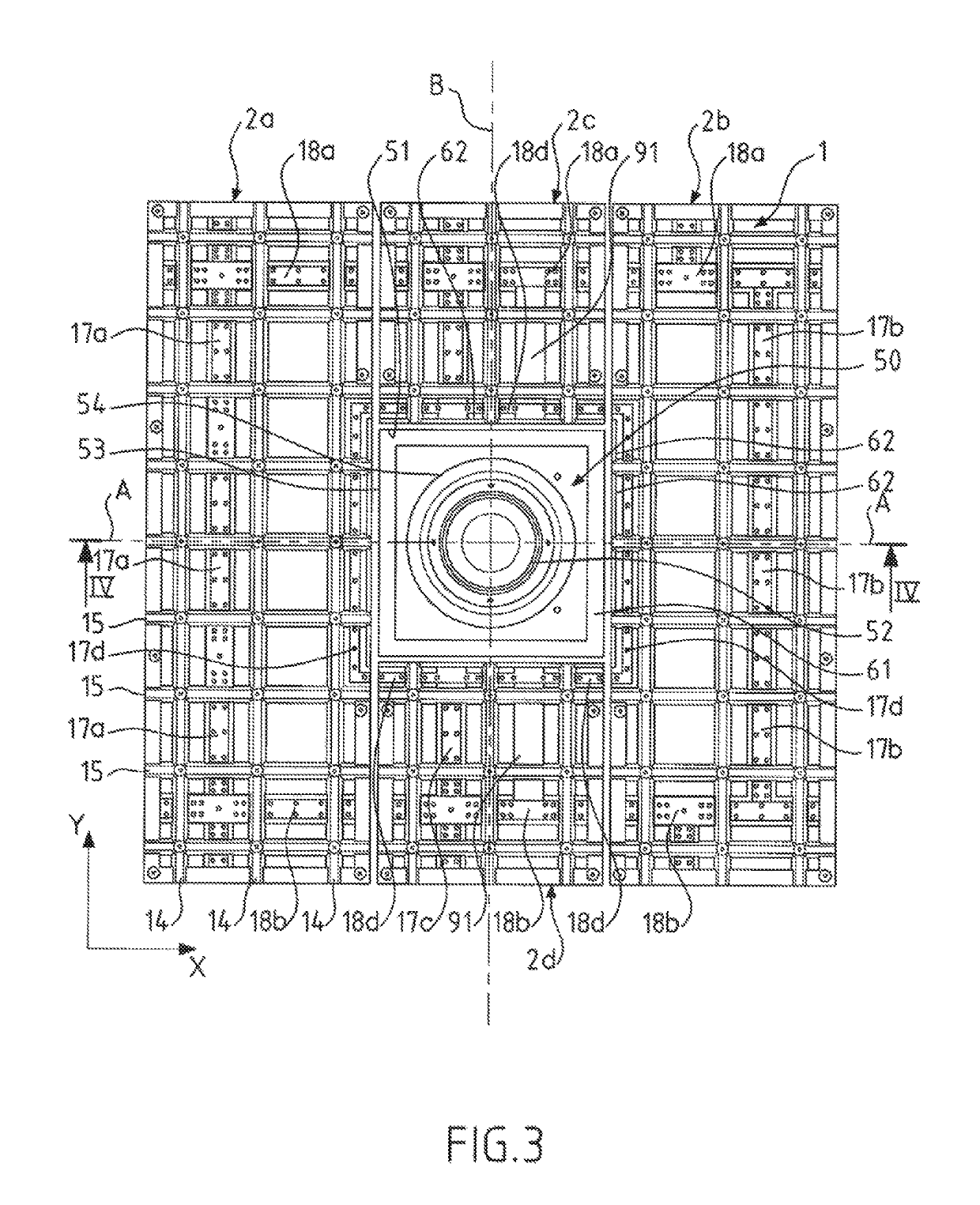
The invention proposes a tank wall with a multilayer structure that allows for the passage of a through-element without creating concentrations of strains in the sealing membrane around the element. The structure is designed to withstand thermal and mechanical stresses and is relatively easy to connect to adjacent zones of the tank wall. This design also creates an offset between the edges of the insulating panels and the edges of the corrugated metal sheets, which simplifies the connection to the adjacent zones of the tank wall.

Problems solved by technology

However, when a diameter of the support foot exceeds two corrugation intervals, these structures provide for locally shifting the routing of the corrugations to form more complex networks of corrugations.
Now, increasing the complexity of the network of corrugations in this way can prove complicated to implement, particularly in the case where the routing of the corrugations has an effect on other elements of the tank wall, which must then be adapted to the more complex networks of corrugations.
Similar problems are also likely to arise in the top wall of the tank, for example in a vapor-collecting duct or in the bottom wall of the tank, for example in a sump structure or any other element passing through a singular zone of the tank wall.

Method used


Image

  • Sealed and thermally insulated tank fitted with a through-element
  • Sealed and thermally insulated tank fitted with a through-element
  • Sealed and thermally insulated tank fitted with a through-element

Examples


Embodiment Construction

)

[0043]By convention, the terms “outer” and “inner” are used to define the relative position of one element in relation to another, by reference to the interior and the exterior of the tank. Furthermore, the longitudinal direction of a rectangular parallelepipedal element should be understood to be the direction corresponding to the side of greatest dimension of the rectangle.

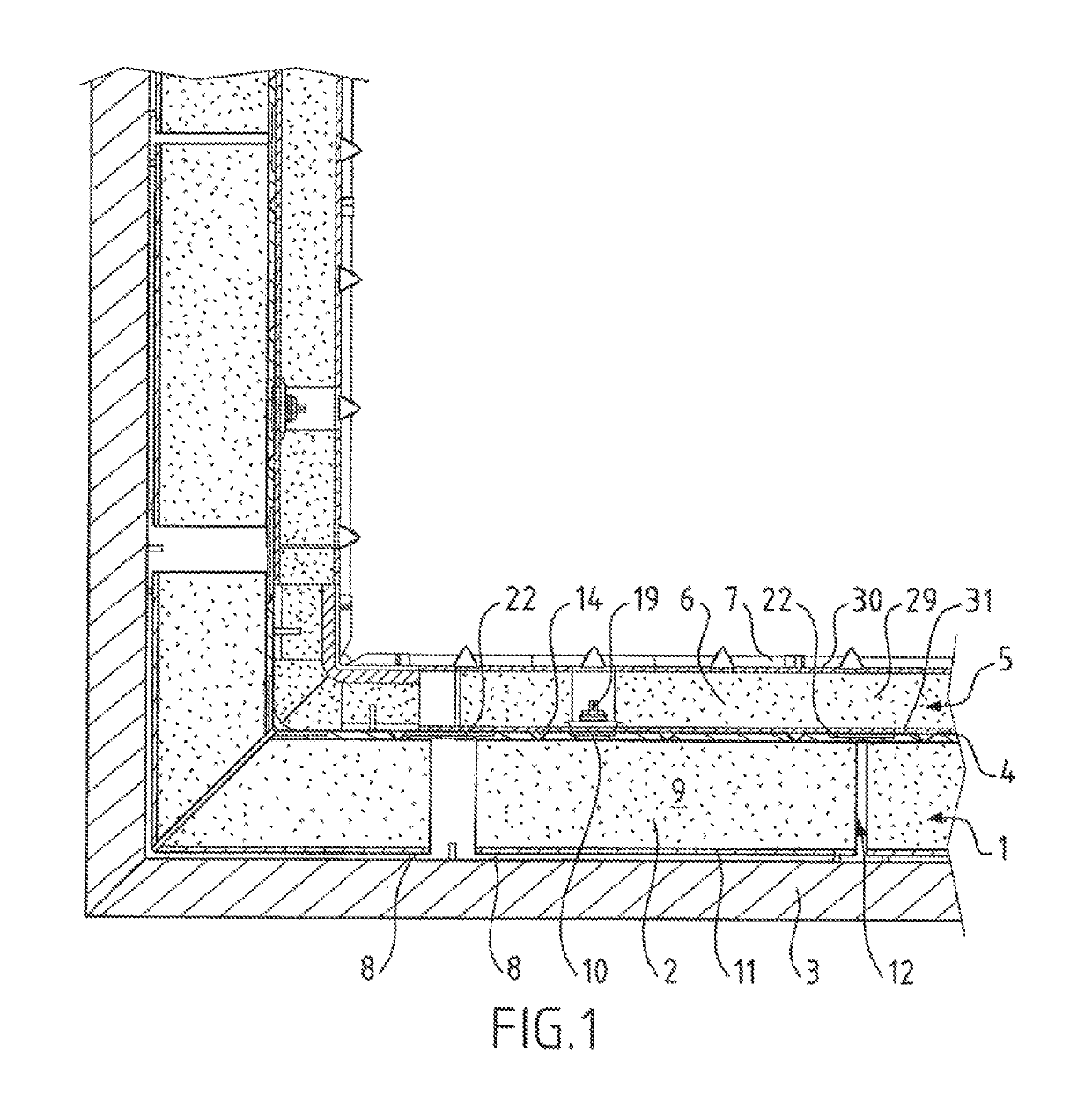
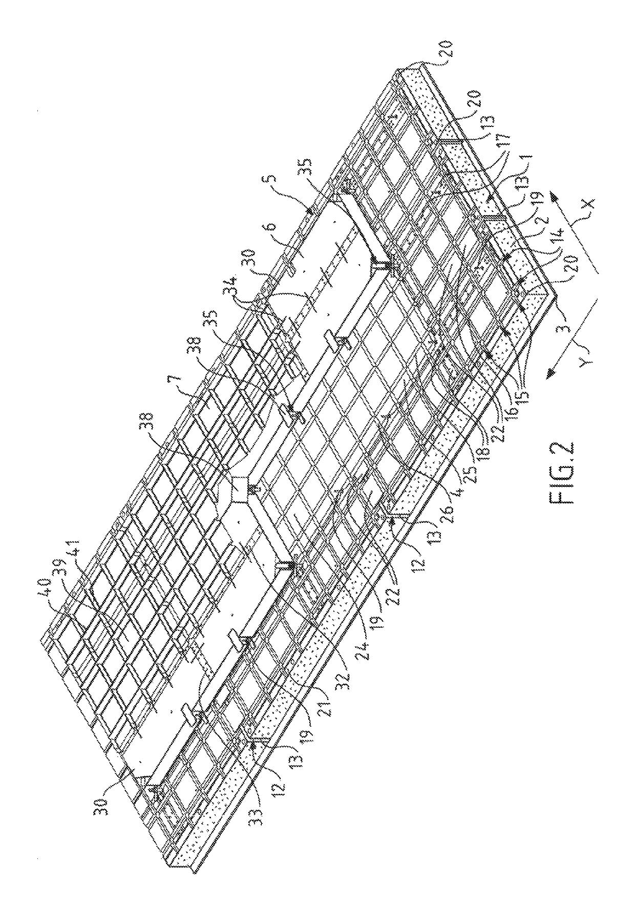
[0044]In relation to FIGS. 1 and 2, the multilayer structure of a sealed and thermally insulating liquefied natural gas storage tank is described. Each wall of the tank comprises, from the outside to the inside of the tank, a secondary thermally insulating barrier 1 comprising insulating panels 2 juxtaposed with and anchored to a bearing wall 3 by secondary retaining members 8, a secondary sealing membrane 4 borne by the insulating panels 2 of the secondary thermally insulating barrier 1, a primary thermally insulating barrier 5 comprising insulating panels 6 juxtaposed with and anchored to the insulating panel...


PUM

PropertyMeasurementUnit
Lengthaaaaaaaaaa
Thicknessaaaaaaaaaa
Widthaaaaaaaaaa

Abstract

A sealed and thermally insulating tank wherein the distance between two adjacent corrugations of the corrugated metal sheets of the sealing membrane is equal to a predetermined corrugation interval io, the sealing membrane comprising, around a through-element:two notched rectangular metal plates 3io wide in the first direction and 7io long in the second direction, which are symmetrical to one another, each notched rectangular metal plate having three outer edges disposed in line with a plurality of anchor plates and welded onto the first plurality of anchor plates and an inner edge having a notch formed to avoid cutting a square window through which the through-element passes,and two metal retrofit plates disposed between the non-notched portions of the inner edges of the two notched rectangular metal plates.

Description

CROSS-REFERENCE TO RELATED APPLICATIONS AND CLAIM TO PRIORITY[0001]This application is a national stage application of International Application No. PCT / FR2016 / 050891 filed Apr. 15, 2016, which claims priority to French Patent Application No. 1553496 filed Apr. 20, 2015, the disclosures of which are incorporated herein by reference and to which priority is claimed.FIELD OF THE INVENTION[0002]The invention relates to the field of the tanks, which are sealed and thermally insulating, with membranes, for the storage and / or transportation of fluid, such as a cryogenic fluid.[0003]Sealed and thermally insulating tanks with membranes are employed in particular for the storage of liquefied natural gas (LNG), which is stored, at atmospheric pressure, at approximately −162° C.BACKGROUND OF THE INVENTION[0004]The document WO-A-2011 / 157915 describes a sealed and thermally insulating tank for the storage of liquefied natural gas, of the type which comprises a tank wall fixed to a flat bearing w...

Claims


Application Information

Patent Timeline
IPC IPC(8): F17C3/02F17C13/00F17C6/00F17C9/00
CPCF17C3/027F17C9/00F17C13/004F17C6/00F17C2270/0113F17C2201/0157F17C2201/052F17C2203/0333F17C2203/0358F17C2203/0631F17C2205/018F17C2205/0302F17C2205/0355F17C2209/221F17C2221/033F17C2223/0161F17C2223/033F17C2223/047F17C2227/0135F17C2227/0178F17C2260/01F17C2270/0107
Inventor GIVOLOUP, HILARIONDUCLOY, EDOUARDBOYEAU, MARCPHILIPPE, ANTOINE
Owner GAZTRANSPORT & TECHNIGAZ
Learn More