
Device for automated capsulotomy

a capsulotomy and automated technology, applied in the field of capsulotomy devices and methods, can solve the problems of weakening the capsule, difficult to create the required level of precision in the lens capsule, and capsules may not be able to hold, so as to achieve the effect of higher electrical resistan

Active Publication Date: 2019-07-30
MYNOSYS CELLULAR DEVICES INC
View PDF30 Cites 4 Cited by
  • Summary
  • Abstract
  • Description
  • Claims
  • Application Information

AI Technical Summary

Benefits of technology

The device enables precise and efficient cutting of the lens capsule, reducing the risk of radial tears and ensuring proper IOL placement, thereby improving the accuracy and effectiveness of capsulotomy procedures.

Problems solved by technology

Creating an opening in the lens capsule with the required level of precision is a difficult task for a surgeon controlling and guiding conventional handheld cutting instruments and attempting to trace a precise circular route on the lens capsule.
There can also be radial tears in the edge of the hole that greatly weaken the capsule.
As a result of any of these errors, the capsule may not be able to hold the IOL properly, and optimal visual outcome cannot be achieved.
Microsurgery instruments commonly are not sufficiently compact or streamlined in shape, making it difficult for a surgeon to minimize the incision size or possibly risking tears or other damage at the incision site.
Cutting elements or other sharp components are sometimes exposed during insertion, requiring the surgeon to be very precise and creating further risk of collateral damage to tissue when inserting the instrument through the incision.
Once inserted, instruments are often not easily manipulated and the surgeon may be forced to handle and move multiple separate pieces in a small space.
Any of these problems can make it very difficult for a surgeon to access a second layer of tissue behind a first layer, particularly when the second layer is tissue in a very small area, such as within the eye.

Method used


Image

  • Device for automated capsulotomy
  • Device for automated capsulotomy
  • Device for automated capsulotomy

Examples


Embodiment Construction

[0082]The figures and the following description relate to various embodiments of the invention by way of illustration only. It should be noted that from the following discussion, alternative embodiments of the structures and methods disclosed herein will be readily recognized as viable alternatives that may be employed without departing from the principles of what is claimed.

[0083]Reference will now be made in detail to several embodiments, examples of which are illustrated in the accompanying figures. It is noted that wherever practicable similar or like reference numbers may be used in the figures and may indicate similar or like functionality. The figures depict embodiments of the disclosed system (or method) for purposes of illustration only. One skilled in the art will readily recognize from the following description that alternative embodiments of the structures and methods illustrated herein may be employed without departing from the principles described herein.

[0084]Embodime...


PUM

PropertyMeasurementUnit
thicknessaaaaaaaaaa
thicknessaaaaaaaaaa
thickaaaaaaaaaa

Abstract

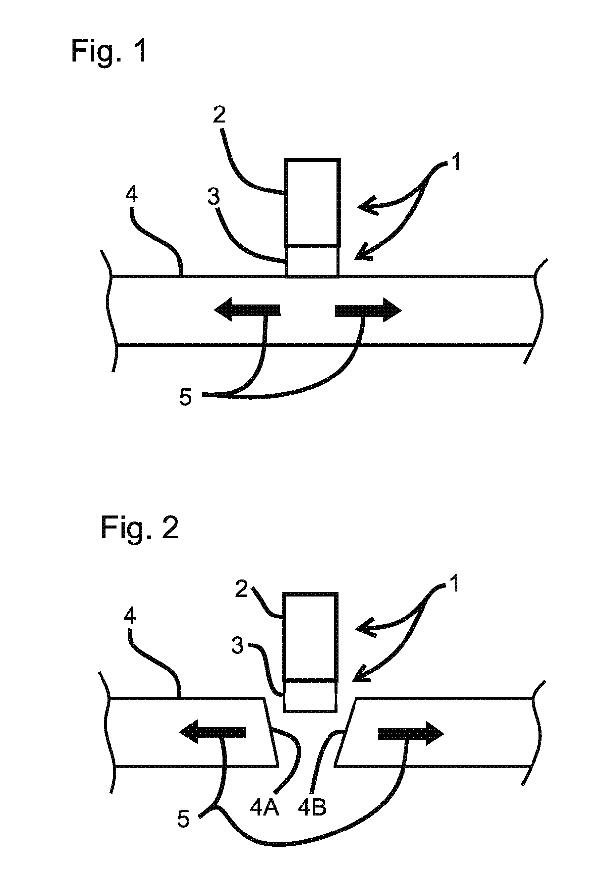
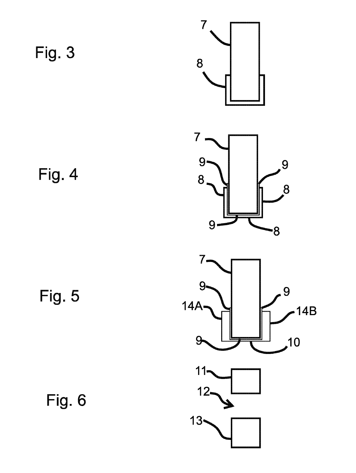
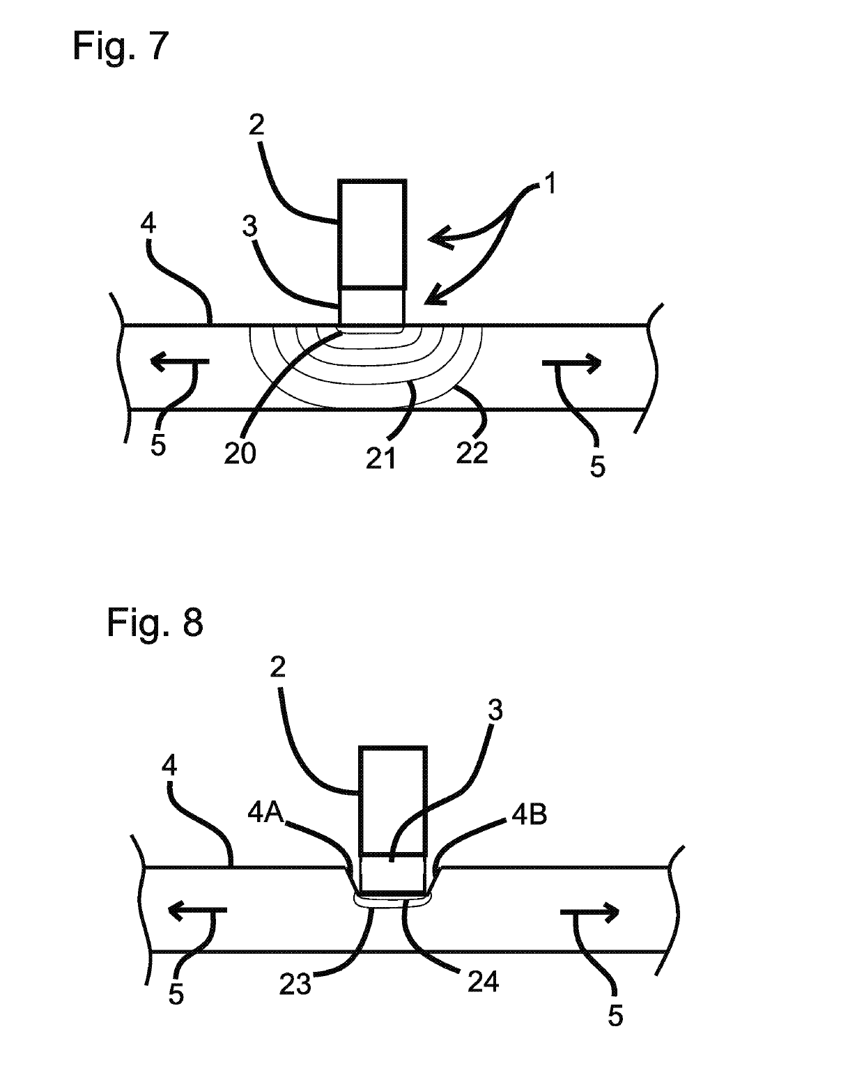
A surgical device is disclosed for cutting tissue, including for performing a capsulotomy of a lens capsule of an eye. This device includes a reversibly collapsible cutting element for cutting a portion of a capsule membrane of the eye. The cutting element includes an outer layer, an inner layer, and a bottom layer that has a higher electrical resistance than the electrical resistance of the outer layer and the inner layer. The bottom layer is configured to conduct an electrical current between the outer layer and the inner layer, which causes a temperature increase in the bottom layer for cutting tissue.

Description

CROSS-REFERENCE TO RELATED APPLICATIONS[0001]This application is the National Stage of PCT Application No. PCT / US2013 / 060988 filed Sep. 20, 2013, which claims priority to U.S. Provisional Application No. 61 / 703,514, filed Sep. 20, 2012, each of which are incorporated herein by reference in their entirety.STATEMENT REGARDING FEDERALLY SPONSORED RESEARCH OR DEVELOPMENT[0002]This invention was made with government support under Grant Numbers 3R44EY021023-03S1, 5R44EY021023-03, 2R44EY021023-04, and 2R44EY021023-02, awarded by the National Institutes of Health. The government has certain rights in the invention.BACKGROUND[0003]Technical Field[0004]This disclosure relates to devices and methods for performing a capsulotomy, and more specifically, devices and methods for using an electrical cutting element to cut a membrane of the eye during a capsulotomy.[0005]Description of the Related Art[0006]Lens cataract is the leading cause of blindness worldwide and surgical treatment by cataract r...

Claims


Application Information

Patent Timeline
Patent Type & Authority Patents(United States)
IPC IPC(8): A61B18/08A61F9/007A61B18/00
CPCA61F9/00754A61B18/082A61F9/0079A61B2018/00601A61B2018/00107A61B2018/00321
Inventor KELLER, CHRISTOPHER GUILD
Owner MYNOSYS CELLULAR DEVICES INC
Learn More