
Single-echo imaging with nonlinear magnetic gradients

a single-echo imaging and nonlinear magnetic gradient technology, applied in the field of single-echo imaging with nonlinear magnetic gradients, can solve the problems of affecting the accuracy of single-echo imaging, etc., to achieve the effect of efficient encoding of signals, easy resolution, and easy spatial localization

Active Publication Date: 2019-07-16
YALE UNIV
View PDF14 Cites 0 Cited by
  • Summary
  • Abstract
  • Description
  • Claims
  • Application Information

AI Technical Summary

Benefits of technology

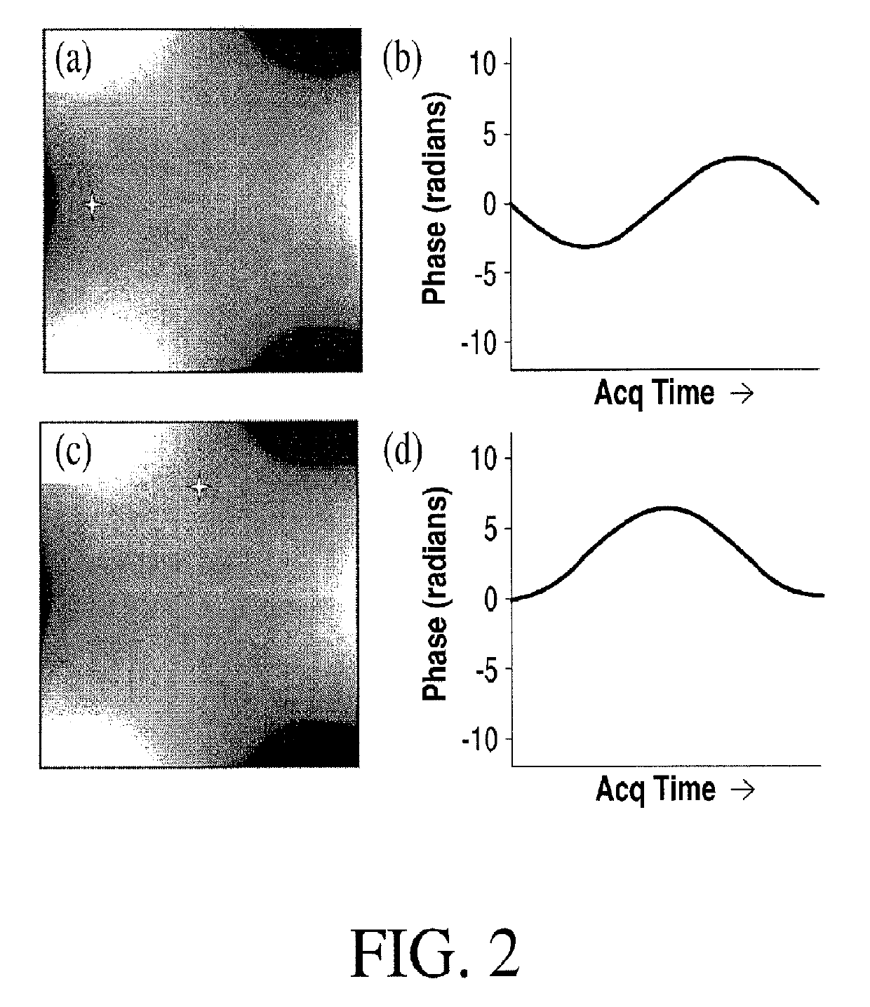
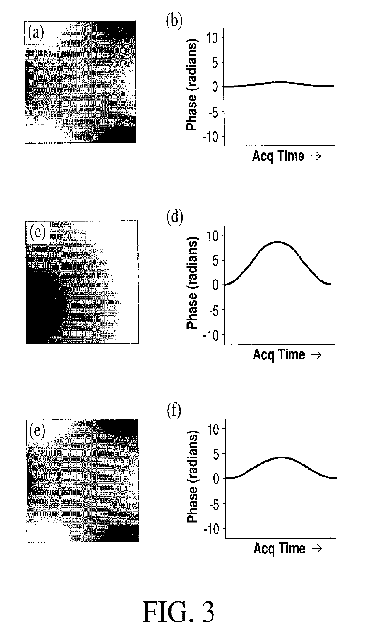
[0014]It is, therefore, an object of the present invention to provide a method for efficiently encoding signals in an MRI image through a combination of parallel receiver coils, and nonlinear gradient encoding that varies dynamically in such a manner as to impose a unique phase / frequency time varying signal on each pixel in the field of view (FOV). Any redundancies are designed such that they are easily resolved by the receiver coil sensitivity profiles. Since each voxel has an essentially identifiable complex temporal signal, spatial localization is easily achieved with only a single echo acquisition.
[0015]Accordingly, it is an object of the present invention to provide a method for increasing imaging speeds in MRI by using nonlinear magnetic gradient fields combined with parallel receiver technology and dynamic modulation of the nonlinear magnetic gradient fields in such a manner that a unique signature is imposed on each region within the field of view such that spatial localization is achieved. The method is achieved by generating nonlinear magnetic gradient fields for spatial encoding of nuclear spin magnetization, applying pulse sequences composed of the nonlinear magnetic gradient fields and radio frequency fields to a targeted subject to generate magnetic resonance signals, detecting the generated magnetic resonance signals, storing the generated magnetic resonance signals, and processing the generated magnetic resonance signals to reconstruct spectra and images of the object.
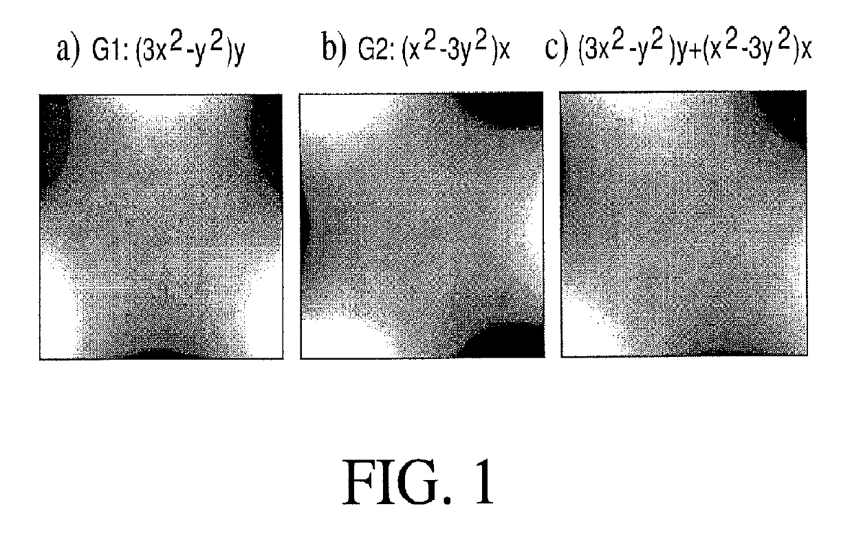
[0019]It is also an object of the present invention to provide a method wherein the step of generating includes electronically combining C2 (2nd Order Magnetic Gradient defined as x2−y2), S2 (2nd Order Magnetic Gradient defined as xy), C4 (4th Order Magnetic Gradient defined as x46x2y2+y4) S4 (4rd Order Magnetic Gradient defined as 4(yx3+xy3), and / or Z2 (2nd Order Magnetic Gradient defined as z2−(x2+y2) / 2)) or a comparable shape to aid in encoding the center of the field of view.
[0028]It is another object of the present invention to provide an MRI system wherein the nonlinear magnetic gradient field is generated by electronically combining C2 (2nd Order Magnetic Gradient defined as x2−y2), S2 (2nd Order Magnetic Gradient defined as xy), C4 (4th Order Magnetic Gradient defined as x4+6x2y2+y4), S4 (4th Order Magnetic Gradient defined as 4(yx3+xy3), and / or Z2 (2nd Order Magnetic Gradient defined as z2−(x2+y2) / 2)) or a comparable shape to aid in encoding the center of the field of view.

Problems solved by technology

Magnetic Resonance Imaging (MRI) is notoriously slow.
This severely limits throughput, makes costs high, and decreases the availability of MRI to a broader community.
These gradients, however, can be inefficient with regard to information gathered from the coil sensitivities, resulting in longer scan times and / or reduced image resolution.
The limited flexibility in changing coil profiles makes implementation on an anatomy-constrained geometry difficult.
This research has focused on increasing the number of receiver coils to localize the sensitivity, only to face issues of ballooning cost and diminishing returns.
Hardware costs increase dramatically with the number of coils since each coil must use a separate receiver, cabling, pre-amplifier, and so on.
The difficulty of constructing large coil arrays is nontrivial as elements must be de-coupled.
Increasing coil number reduces the g-factor, a pixel by pixel measure of noise amplification, but drives the cost much higher and exacerbates the decoupling problem.
Moving to higher fields and including spatially selective parallel transmission pulses show promise, but fundamentally does not address the underlying encoding problem.
Improvements have been made in SENSE and GRAPPA reconstructions to preserve reconstruction quality, but these penalize acceleration in image acquisition.

Method used


Image

  • Single-echo imaging with nonlinear magnetic gradients
  • Single-echo imaging with nonlinear magnetic gradients
  • Single-echo imaging with nonlinear magnetic gradients

Examples


Embodiment Construction

[0042]Referring now to the various drawings, the present invention increases imaging speeds in MRI by using nonlinear magnetic gradients combined with parallel receiver technology and dynamic modulation of these magnetic gradients in such a manner that a unique signature is imposed on each region within the field of view such that spatial localization is achieved.

[0043]Before proceeding with the detailed description of the present invention, it is appreciated that MRI uses spatially-varying magnetic fields, termed gradients, in order to spatially localize signals. Fundamentally, magnetic resonance imaging differs from spectroscopy through the use of gradients that assign different frequency codes to separate spatial regions in the area to be imaged. The Larmor precession equation states that the frequency of the RF signal applied in MRI processing be proportional to the magnetic field intensity. While prior research (as discussed above) has focused on efficient methods and apparatus...


PUM


Abstract

Efficient encoding of signals in an MRI image is achieved through a combination of parallel receiver coils, and nonlinear gradient encoding that varies dynamically in such a manner as to impose a unique phase / frequency time varying signal on each pixel in the field of view. Any redundancies are designed such that they are easily resolved by the receiver coil sensitivity profiles. Since each voxel has an essentially identifiable complex temporal signal, spatial localization is easily achieved with only a single echo acquisition.

Description

CROSS REFERENCE TO RELATED APPLICATION[0001]This application is a § 371 of International Application No. PCT / US2014 / 066569, entitled “SINGLE-ECHO IMAGING WITH NONLINEAR MAGNETIC GRADIENTS”, filed Nov. 20, 2014, which claims the benefit of U.S. Provisional Patent Application Ser. No. 61 / 963,072, entitled “SINGLE-ECHO IMAGING WITH NONLINEAR GRADIENTS,” filed Nov. 22, 2013.[0002]This invention was made with government support under EB012289 awarded by National Institute of Health. The government has certain rights in the invention.FIELD OF THE INVENTION[0003]The invention relates to magnetic resonance imaging. More particular, the invention relates to magnetic resonance imaging using continuous readout with nonlinear magnetic gradients and parallel receiver coils for fast imaging.BACKGROUND[0004]Magnetic Resonance Imaging (MRI) is notoriously slow. Clinical exams typically take on the order of 1 hour per patient. This severely limits throughput, makes costs high, and decreases the avai...

Claims


Application Information

Patent Timeline
Patent Type & Authority Patents(United States)
IPC IPC(8): G01R33/48G01R33/561
CPCG01R33/5611G01R33/561G01R33/4826G01R33/4824
Inventor CONSTABLE, ROBERT TODDGALIANA, GIGI
Owner YALE UNIV
Learn More