
Process and device for acquisition of data of a counting device measuring pulses delivered by a sensor

a counting device and data acquisition technology, applied in the direction of optical conversion of sensor output, instruments, etc., can solve the problems of lag in relation to the change of value of the counting device, inability to represent the instantaneous real positioning of the mobile unit, and expensive use of high-frequency sampling clocks. , to achieve the effect of less calculation

Active Publication Date: 2019-07-16
DEWESOFT
View PDF8 Cites 0 Cited by
  • Summary
  • Abstract
  • Description
  • Claims
  • Application Information

AI Technical Summary

Benefits of technology

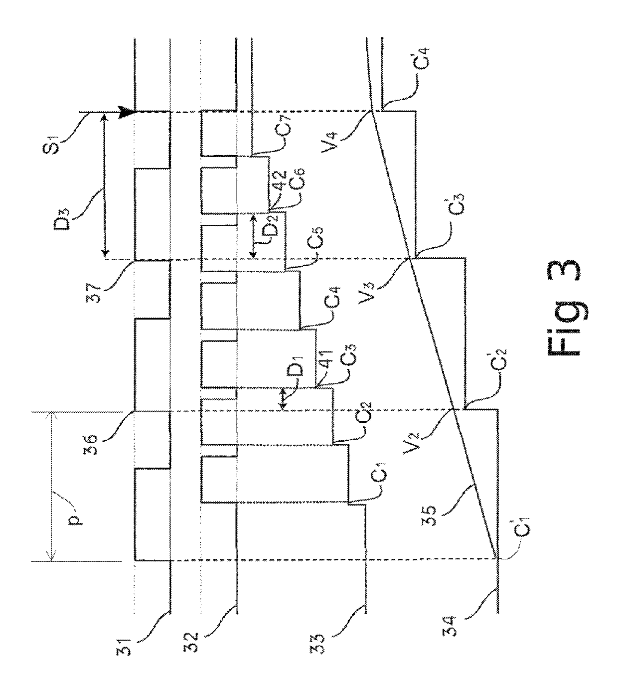
The present patent aims to reduce the CPU load and the size of data storage related to position measurements. It achieves this by calculating an adjustment value based on the source value and the measured time-interval between the sampling and the change of the counting device. The process of measuring the changes in the counting device can be repeated at regular intervals to obtain higher precision. The adjustment value is then stored and analyzed subsequently to obtain the instantaneous positioning of the mobile unit. This results in higher precision, CPU savings, and lower storage costs.

Problems solved by technology

Now, the use of a high-frequency sampling clock is costly, because it involves a high CPU load and recording a large amount of data.
But this solution leads to a lag in relation to the change of value of the counting device.
In consequence, the results of this approximation are not representative of the instantaneous real positioning of the mobile unit.
In consequence, this brings about a higher precision, CPU gain and a lowering of the volume, and therefore of the cost of storage, of the data.
In consequence, if no incrementation of the counting device has taken place between two samplings of source values, the measurement of the time-interval necessary for the calculation of the adjustment value of the source value that was read at the time of the first sampling will not be completed at the time of the second reading.

Method used


Image

  • Process and device for acquisition of data of a counting device measuring pulses delivered by a sensor
  • Process and device for acquisition of data of a counting device measuring pulses delivered by a sensor
  • Process and device for acquisition of data of a counting device measuring pulses delivered by a sensor

Examples


Embodiment Construction

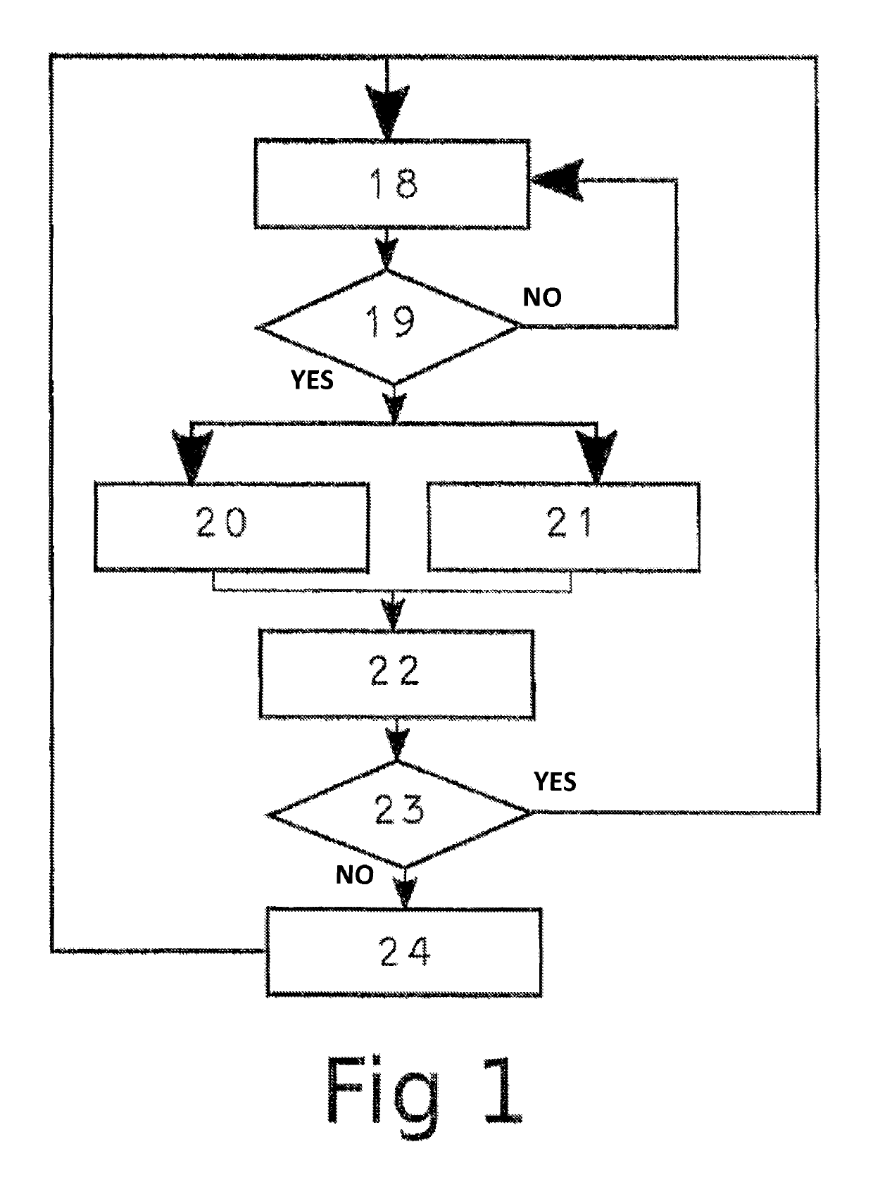
[0059]An embodiment of the process according to the present disclosure, represented in FIG. 1, enables each source value of a counting device to be adjusted by a data acquisition device in order to obtain values that are representative of the positioning of a mobile unit associated with the sensor. The process includes a step 18 of sampling of a datum value C of the counting device, named current sampling C′x, by the data acquisition device. The sampling is carried out in accordance with a sampling frequency corresponding to a sampling period. Then, a test 19 is carried out, in order to determine whether the value C′x is representative of an incrementation of the counting device—that is to say, if this value has not already been read or sampled previously. If the value C′x is not representative of an incrementation, the process is repeated, beginning by a sampling of a new source value in step 18.

[0060]It is noted that C is a count value wherein Cy is the value held by the counting ...


PUM


Abstract

A process for the acquisition of data of a counting device measuring pulses delivered by a sensor can include reading a first datum value of the counting device. The first datum value corresponds to the pulse emitted by the sensor. The process can also include storing in memory the first datum value as a source value. The process can also include measuring a time-interval between said reading and an incremental change of the first datum value of the counting device to a second datum value. The process can also include obtaining a first adjustment value Vx in response to the measured time interval.

Description

BACKGROUND[0001]1. Field[0002]The present disclosure concerns a process for acquisition of data of a counting device measuring pulses delivered by a sensor, and extends to a device designed for the implementation of such a process.[0003]2. Description of Related Prior Art[0004]Counting devices associated with sensors delivering a train of pulses can be used to obtain information on a mobile unit such as the position of the mobile unit and / or its speed and / or its acceleration by measuring the number of pulses that are output by the sensor and / or it can also be used to count the number of pulses delivered by the sensors. A sensor delivering a train of pulses can be an optical sensor, an inductive sensor, a Hall sensor etc. For example, a rotary encoder is a device including a graduated mobile disc exhibiting a certain resolution and coupled to a rotating shaft. In this case the graduations of the disc can be read by means of an optical transmission module and an optical reception modu...

Claims


Application Information

Patent Timeline
Patent Type & Authority Patents(United States)
IPC IPC(8): G04F1/00G01D5/347G01D5/36G01D5/248
CPCG01D5/248G01D5/36G01D5/34715
Inventor KNEZ, JURESOTLER, TILEN
Owner DEWESOFT
Learn More