
Measurement devices and methods

a measurement device and tape technology, applied in the field of measurement devices, can solve the problems of difficult for a user to intentionally or inadvertently pull or push the tape, shorten or lengthen the locked distance associated with the particular locked position, and waste. the effect of frustration

Active Publication Date: 2019-07-16
MJ STEWART INVESTMENTS LLC
View PDF20 Cites 1 Cited by
  • Summary
  • Abstract
  • Description
  • Claims
  • Application Information

AI Technical Summary

Benefits of technology

The solution provides a reliable and accurate method for measuring both inside and outside dimensions, reducing errors and frustration associated with traditional tape measures by locking the tape in place, allowing users to easily transfer measurements without referencing tape markings.

Problems solved by technology

The first named inventor conceived of the present invention while building playhouses, where numerous cuts of identical length were required for boards to be used in construction of the play house, in using a tape measure to take the proper measurement, the measurement was remembered or communicated incorrectly, so that several boards were cut at the incorrect length, resulting in frustration and waste.
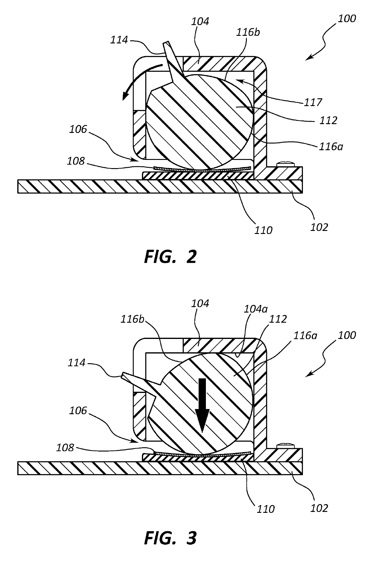
Providing an elastomeric gripping layer that contacts the tape, so as to be involved in the pinching of the tape in some way, provides very tight locking of the tape, making it very difficult for a user to intentionally or inadvertently pull or push the tape in (which would undesirably shorten or lengthen the locked distance associated with the particular locked position).
While this is so, the lock provided by such existing structures is not particularly tight, so that a user may intentionally or inadvertently cause the tape to retract or be further extended by pushing or pulling the tape with a relatively small force.
Such a pushing or pulling force will be insufficient to cause the locking structures described herein to retract or extend the tape.

Method used


Image

  • Measurement devices and methods
  • Measurement devices and methods
  • Measurement devices and methods

Examples


Embodiment Construction

[0038]I. Introduction

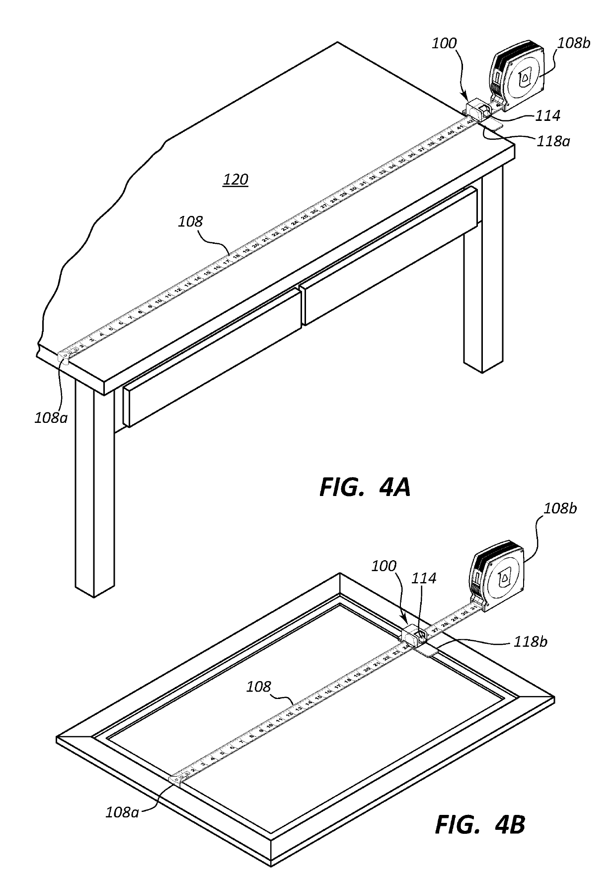
[0039]Embodiments of the disclosure relate to devices and methods that allow a user to take a measurement (e.g., using a tape), and then take that measurement to another location where a board or other material is to be cut, marked, compared, or the like with the measurement. According to one such embodiment, a device that is attachable to, or included with a tape measure may include a base member, a housing supported on the base member including a slot for slidably receiving a tape of the tape measure insertable through the slot of the housing, and an elastomeric gripping layer positioned in the housing, positioned to contact a face of the tape when the tape is locked in a given position during use. A movable pressure locking wedge may be positioned within the housing, which assists in locking the tape in the desired given position as the tape is pinched between the pressure locking wedge and another surface (e.g., the elastomeric gripping layer, or another sur...


PUM


Abstract

A measurement device includes first and second measurement indicia. First indicia (e.g., on the tape) may include numerals regularly spaced to mark inches or other units of length (e.g., 1, 2, 3, etc.). Also included are second indicia, that are non-numeric (e.g., letters, such as A, B, C, etc.) where the second indicia are regularly spaced to mark fractions of inches or other units of length indicated by the first indicia. The second indicia are positioned between adjacent first indicia. For example, the letters (A, B, C, etc.) may be spaced every sixteenth or other fraction of an inch between the “1” and “2” (adjacent first indicia). Where sixteenths are used, the letters A-O are equally spaced, between the adjacent first indicia (e.g., between the “1” and the “2”). The A-O may repeat between each integral number—between “1” and “2”, between “2” and “3” and so forth.

Description

CROSS-REFERENCE TO RELATED APPLICATION[0001]The present application is a continuation-in-part of U.S. patent application Ser. No. 15 / 145,683, filed May 3, 2016, which claims the benefit of U.S. Provisional Patent Application Ser. No. 62 / 331,264, filed May 3, 2016, entitled “MEASUREMENT DEVICES AND METHODS”. The disclosure of each of the foregoing is herein incorporated by reference in its entirety.BACKGROUND OF THE INVENTION1. The Field of the Invention[0002]The invention relates to measurement devices, e.g., tape measures as used by those engaged in carpentry work, seamstresses, and others.2. The Relevant Technology[0003]Tape measures have been available for decades, and have changed little over the past few decades. One problem frequently encountered by anyone familiar with use of a tape measure is the necessity of remembering and / or communicating the value of a measured length. For example, a person often will measure a given space in a first location, and then will need to remem...

Claims


Application Information

Patent Timeline
Patent Type & Authority Patents(United States)
IPC IPC(8): G01B3/00G01B3/10G01B3/02
CPCG01B3/1082G01B3/004G01B3/1084G01B3/02G01B2003/1089G01B2003/1015G01B2003/1058G01B2003/1066G01B3/1041G01B3/1003G01B3/1089
Inventor STEWART, JEFFREY D.PROVOST, WAYNE A.
Owner MJ STEWART INVESTMENTS LLC
Learn More