Image forming apparatus
a technology of forming apparatus and forming tube, which is applied in the direction of electrographic process apparatus, instruments, optics, etc., to achieve the effect of improving image quality
- Summary
- Abstract
- Description
- Claims
- Application Information
AI Technical Summary
Benefits of technology
Problems solved by technology
Method used
Image
Examples
embodiment 1
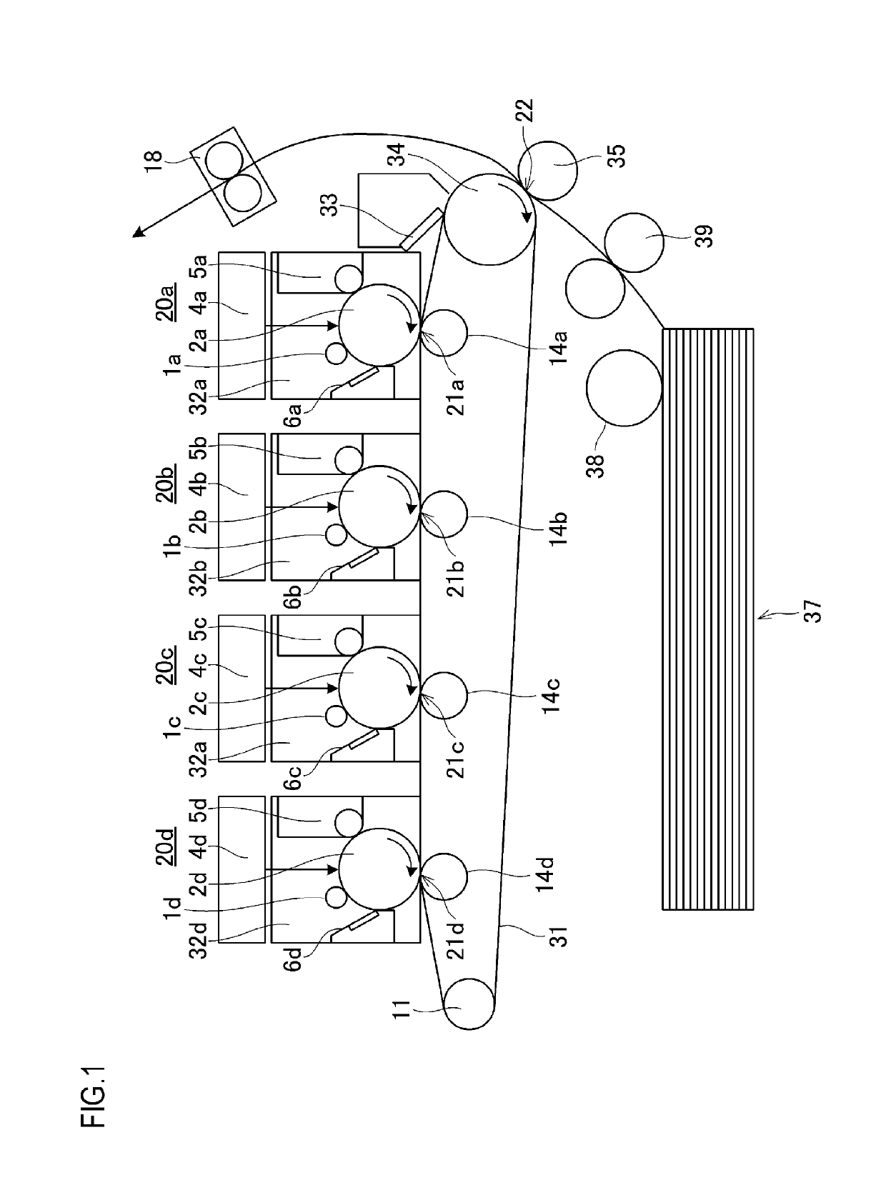
[0027]FIG. 1 is a schematic diagram depicting an example of an image forming apparatus to which the present invention is applied.
[0028]This image forming apparatus is a color image forming apparatus using an intermediate transfer belt 31, and includes a plurality of image forming stations 20 which form images of yellow, magenta, cyan and black (hereafter Y, M, C and Bk) colors. In the following description, an alphabetic character a, b, c or d is attached to the reference sign of a member constituting each image forming station for Y, M, C or Bk, respectively, to distinguish each image forming station. If an alphabetic character is not attached, this means that the description is common to all image forming stations 20.
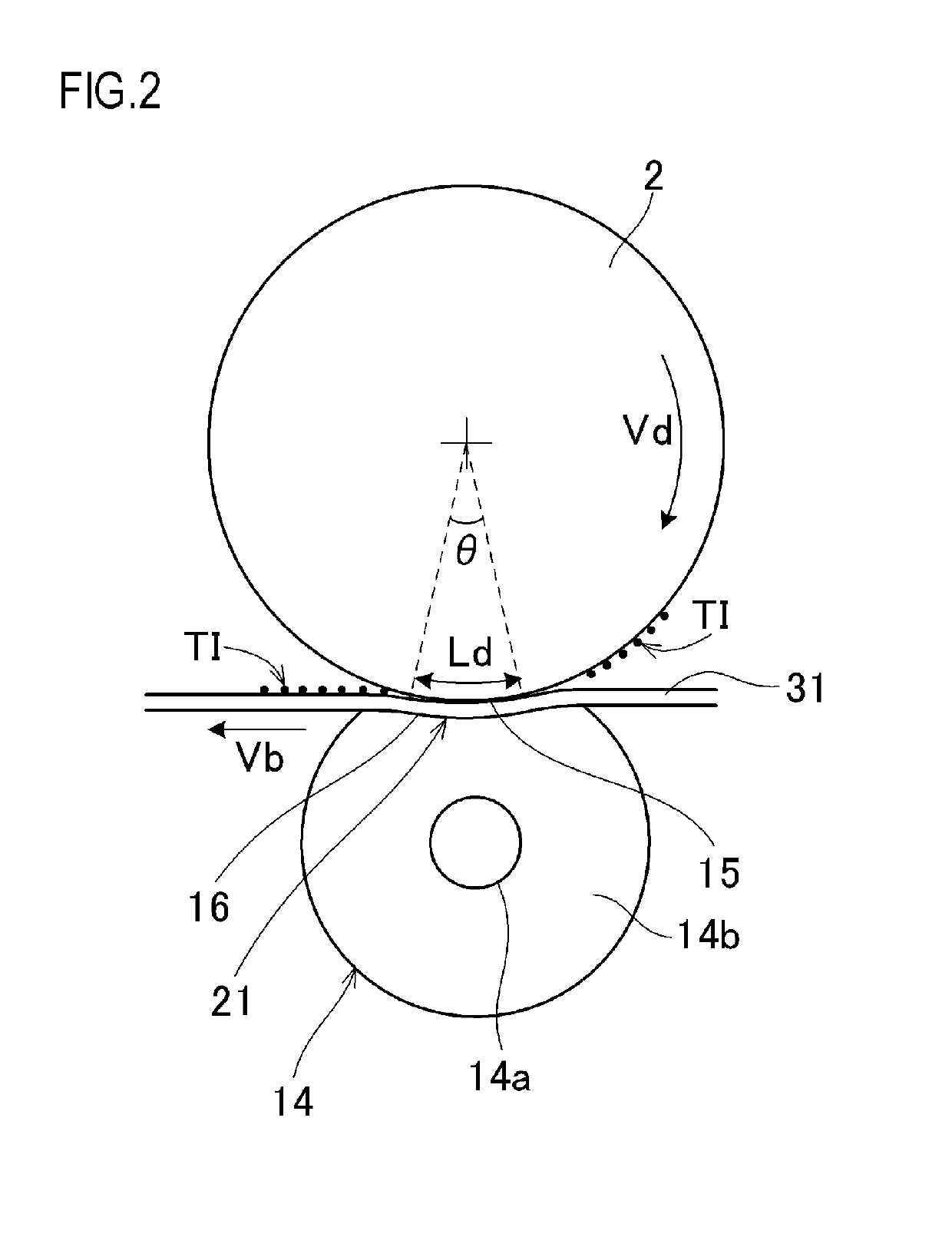
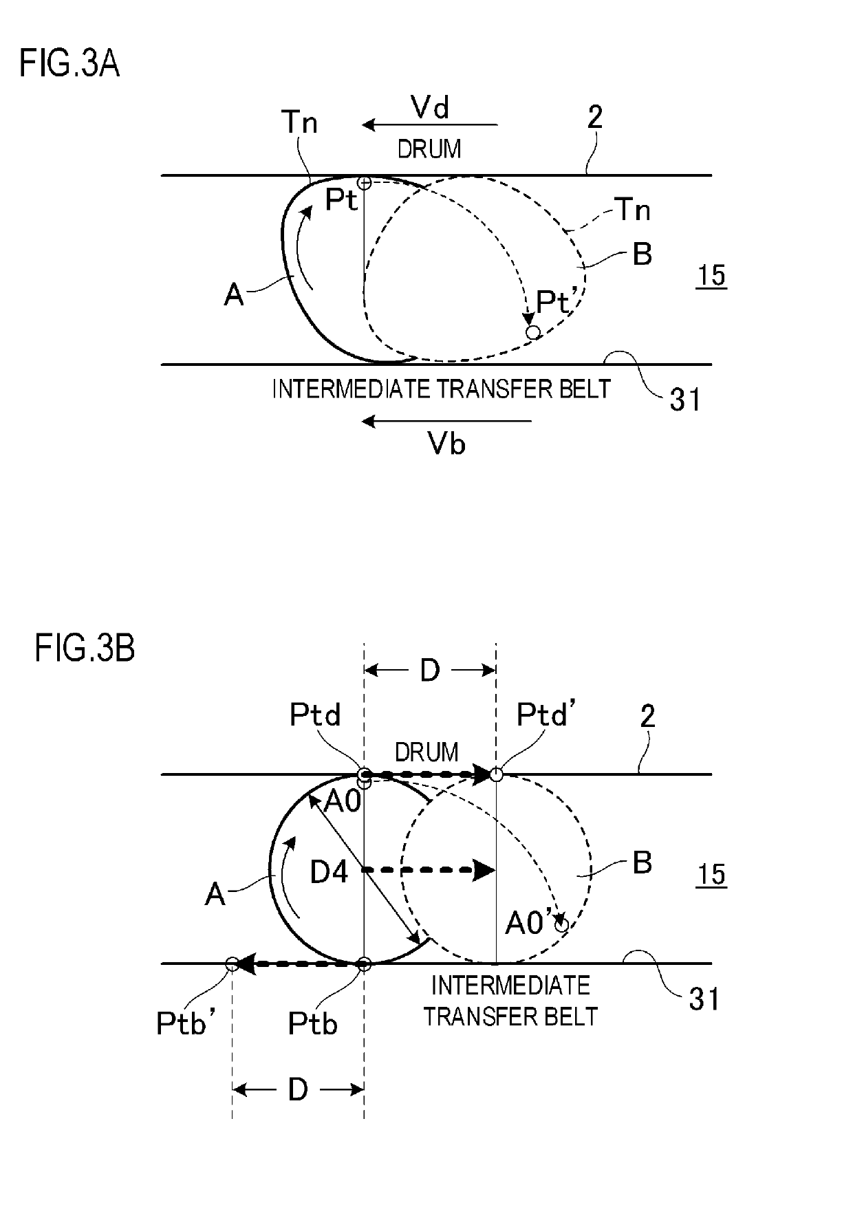
[0029]The intermediate transfer belt 31 is an endless belt which is an elastic body having intermediate resistance, and is wound around a secondary transfer counter roller 34 and a belt driving roller 11, which are disposed distant from each other. If the side of movi...
embodiment 2
[0105]FIGS. 7A and 7B show a primary transfer unit 221 according to Embodiment 2 of the present invention, where FIG. 7A is a cross-sectional view of an image forming station, and FIG. 7B is a diagram depicting the relationship between two image forming stations.
[0106]For the primary transfer member, a primary transfer roller 14, configured by wrapping a core metal 14a with an elastic body 14b (e.g. rubber), is normally used as in the case of Embodiment 1, but in Embodiment 2, a metal roller 214 constituted only by a rigid metal body is used. In the configuration of using the metal roller 214, the primary transfer unit 221 is disposed on the upstream side or downstream side of the photosensitive drum 2 in the transporting direction of the intermediate transfer belt 31, with offsetting of the metal roller 214. By disposing the metal roller 214 in an offset position, the intermediate transfer belt 31 is not sandwiched between the photosensitive drum 2 and the metal roller 214, and the...
embodiment 3
[0115]Embodiment 3 of the present invention will be described next.
[0116]The upper limit value of the shift amount of Embodiment 1 is determined based on the image expansion guaranteeing the resolution specified for the image forming apparatus, but in the case of a low resolution image forming apparatus, the upper limit value of the shift amount becomes high enough to visually recognize the deterioration of the image quality of the printed matter, which is not desirable.
[0117]In Embodiment 3, the upper limit value of the shift amount is specified based on the result of a subjective evaluation experiment, where the level of image deterioration is determined based on subjectivity.
[0118]For the evaluation pattern, the character “” in Mincho font was used, and a 6-point single color character and a 6-point single color outline character were evaluated. In the evaluation environment, a D50 light source illumination was used, and a subjective evaluation experiment was performed with 10 in...
PUM
 Abstract
Description
Claims
Application Information
 - R&D
- Intellectual Property
- Life Sciences
- Materials
- Tech Scout
- Unparalleled Data Quality
- Higher Quality Content
- 60% Fewer Hallucinations
Browse by: Latest US Patents, China's latest patents, Technical Efficacy Thesaurus, Application Domain, Technology Topic, Popular Technical Reports.
© 2025 PatSnap. All rights reserved.Legal|Privacy policy|Modern Slavery Act Transparency Statement|Sitemap|About US| Contact US: help@patsnap.com


