
Substrate pre-scanning for high throughput microscopy

a microscopy and substrate technology, applied in the field of substrate prescanning for high throughput microscopy, can solve the problems of limiting the speed and efficiency of high throughput imaging methods, introducing time-delays, and affecting sample focusing, so as to facilitate sample focusing, the effect of reducing the number of samples

Inactive Publication Date: 2019-05-07
MASSACHUSETTS INST OF TECH
View PDF35 Cites 1 Cited by
  • Summary
  • Abstract
  • Description
  • Claims
  • Application Information

AI Technical Summary

Benefits of technology

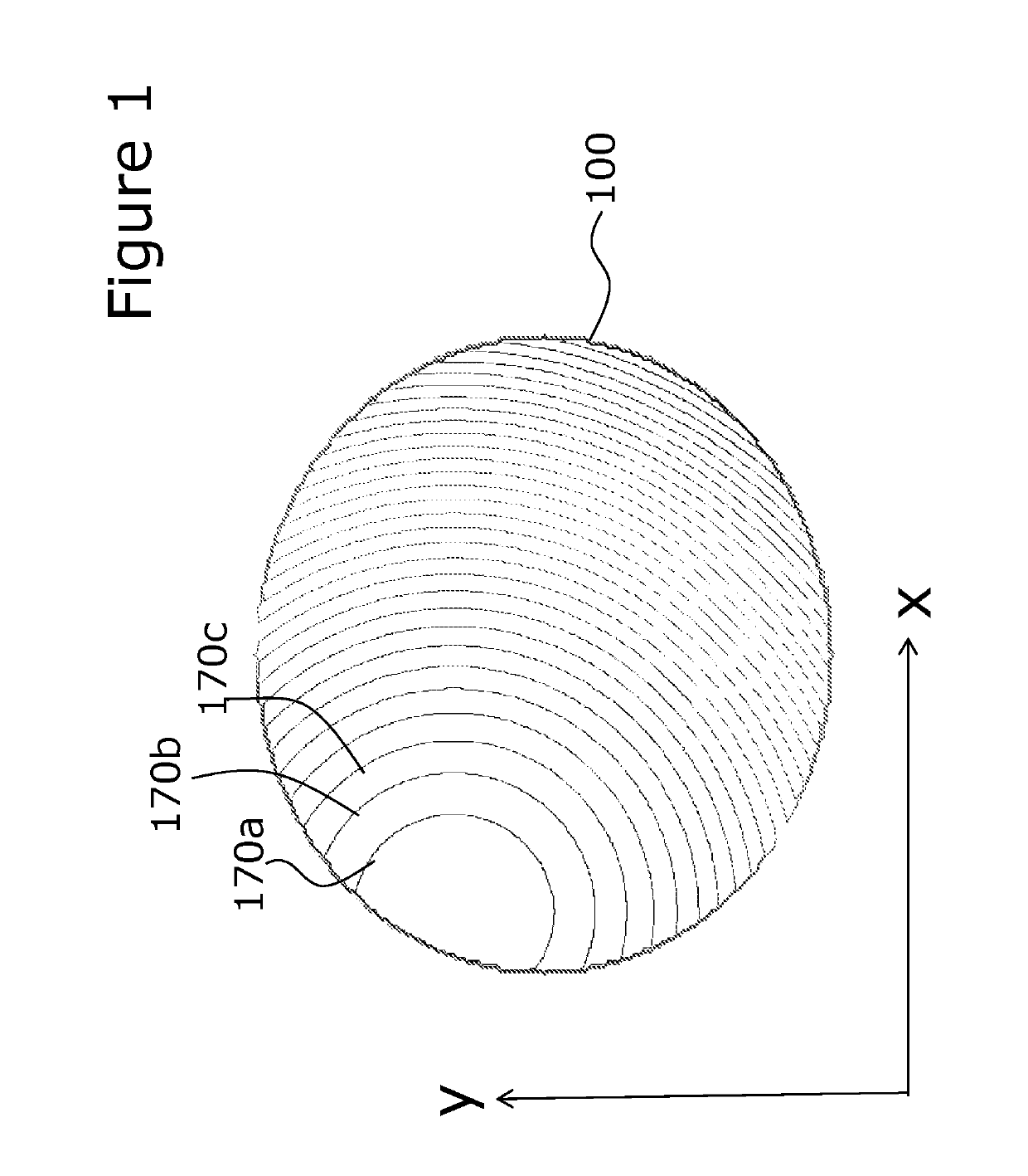
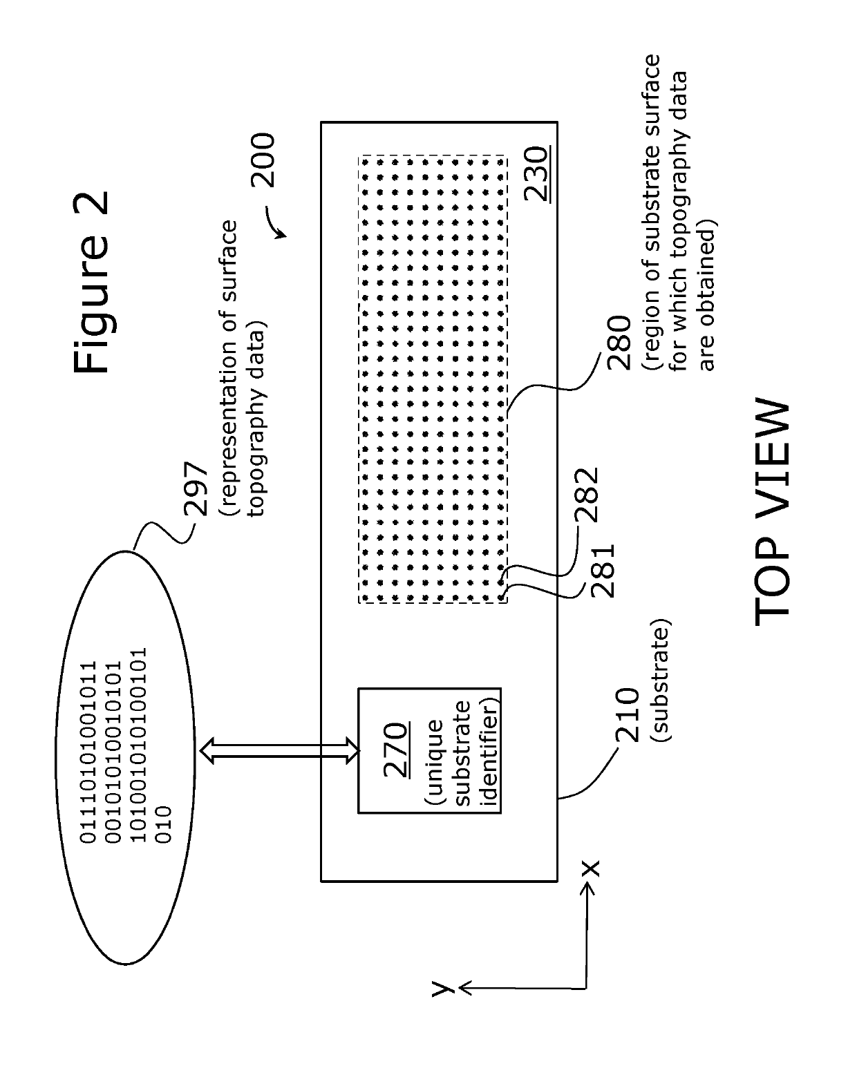
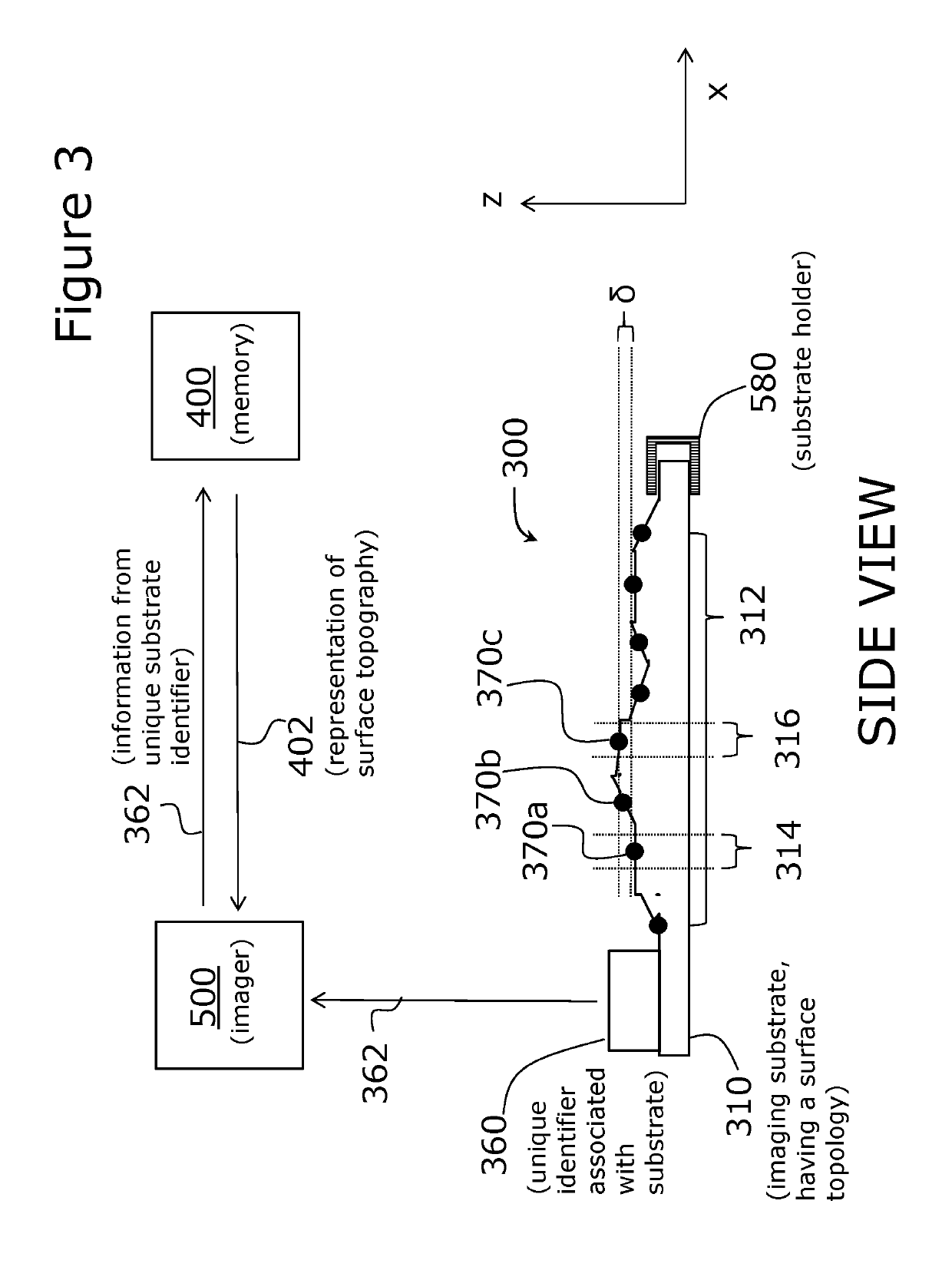
[0004]An embodiment of the present invention relates to a recognition that non-uniformities in substrate thickness and surface topography contribute significantly to the need for auto-focusing on a sample deposited thereon, and that these auto-focusing needs can be reduced or eliminated by measuring and storing substrate topography for later retrieval by an imaging system that can use the topographic information to help set appropriate focal parameters.
[0005]More specifically, imaging substrates, such as microscopy slides and Petri dishes, can vary in thickness, both from one substrate to the next, and from one region to the next on a given substrate. These variations alter the distance between the sample and the objective lens, and can require re-focusing when changing substrates and when imaging different regions of the same substrate. Measuring and storing substrate-specific topographical information for later recall can facilitate focusing by allowing a microscopy system to compensate for the topographical variations (e.g., by a corresponding change in a focal parameter), thereby reducing, or even eliminating, the need for traditional autofocus methods.

Problems solved by technology

Focus related time delays can be significant, for example, when a study requires imaging multiple fields of view, such that refocusing is required between images.
Focus-related time-delays can limit the speed and efficiency of high throughput imaging methods.
Automating focusing (“auto-focusing”) technology, present in many automated pathology slide scanners and automated microscopes, has provided improvements over conventional focusing, but can still introduce time-delays, which can be particularly significant for high throughput work.

Method used


Image

  • Substrate pre-scanning for high throughput microscopy
  • Substrate pre-scanning for high throughput microscopy
  • Substrate pre-scanning for high throughput microscopy

Examples


Embodiment Construction

[0020]A description of example embodiments of the invention follows.

[0021]Focusing can be time-consuming. Focus-related time delays can be particularly significant when a study requires imaging multiple fields of view, such that refocusing is required between images. Focus-related time-delays can limit the speed and efficiency of high throughput imaging methods.

[0022]Automating focusing (“auto-focusing”) technology, present in many automated pathology slide scanners and automated microscopes, has provided improvements over conventional, manual focusing methods but still suffers from significant limitations or drawbacks. For example, although a sample can be automatically imaged at varying distances from the objective lens until optimal focal parameters are determined, methods that require taking several images are time-consuming and can produce fluorescence photo-bleaching of the sample. As another example, although laser-range finders can aid focusing by estimating the distance bet...


PUM


Abstract

Non-uniformities in substrate thickness and surface topography contribute significantly to the need for auto-focusing on a sample deposited thereon. These auto-focusing needs can be reduced or eliminated by measuring and storing substrate surface topography for later retrieval by an imaging system that can use the topographic information to help set appropriate focal parameters. These steps can be done in advance of an imaging experiment to reduce focus-related delays during the experiment. Topographic information can be stored, for example, in a database, associated with a representation of a unique substrate identifier; entry of the representation retrieves the topographic information. As another example, topographic information can be stored in an encoding device associated with the substrate.

Description

RELATED APPLICATION[0001]This application claims the benefit of U.S. Provisional Application No. 62 / 157,457, filed on May 5, 2015. The entire teachings of the above application are incorporated herein by reference.BACKGROUND OF THE INVENTION[0002]In microscopy, proper focus on a sample is essential for image quality. Many image quality problems in pathology slide scanners, for example, are related to improper focusing on the sample. There is a need for improved systems, methods, and imaging accessories that can help to facilitate focusing on samples.SUMMARY OF THE INVENTION[0003]Improved systems, methods, and imaging accessories facilitate focusing on samples, and can be used, for example, in high throughout applications where focus-related time delays can be particularly significant. Focus related time delays can be significant, for example, when a study requires imaging multiple fields of view, such that refocusing is required between images. Focus-related time-delays can limit th...

Claims


Application Information

Patent Timeline
Patent Type & Authority Patents(United States)
IPC IPC(8): B01L3/00G06K9/00G06K9/20G01B11/06G02B21/24G06K19/02G06K19/06G02B21/34G02B21/36G06V10/10
CPCG06K19/022B01L3/54G01B11/0608G02B21/241G02B21/34G02B21/365G06K9/20G06K19/06037G06K19/06159G06K9/00127B01L2300/0822B01L2200/143B01L2300/021B01L2300/022G06V20/69G06V10/10
Inventor DAVE, SHIVANG R.SERRANO, GERMAN GONZALEZ
Owner MASSACHUSETTS INST OF TECH
Learn More