Rail conveyor system with vertical carriage return

a conveyor system and rail technology, applied in the direction of conveyors, transportation and packaging, earth-moving drilling and mining, etc., can solve the problems of limited space at either or both the head and tail end and unsuitable for many delivery situations, so as to reduce the time required for maintenance

Active Publication Date: 2019-05-07
NEWCASTE INNOVATION LTD
View PDF17 Cites 1 Cited by
  • Summary
  • Abstract
  • Description
  • Claims
  • Application Information

AI Technical Summary

Benefits of technology

[0014]In one form the flexibility is achieved by providing compressible blocks as mountings between supports for the wheels and supports for the carry belt.
[0022]Alternatively, the carriages are preferably fixed to the rope by means of a mechanical fastener. In one form, the mechanical fastener is a quick action fastener designed for quick release of the carriages from the rope. This enables reduce time required for maintenance of the carriages and / or rope.

Problems solved by technology

There are however many situations where space is limited at either or both of the head and tail end of the conveyor system and where it is necessary to redirect the carriages from the delivery run to the return run using only a narrow footprint.
This wide footprint is not suitable in many delivery situations.

Method used


Image

  • Rail conveyor system with vertical carriage return
  • Rail conveyor system with vertical carriage return
  • Rail conveyor system with vertical carriage return

Examples


Embodiment Construction

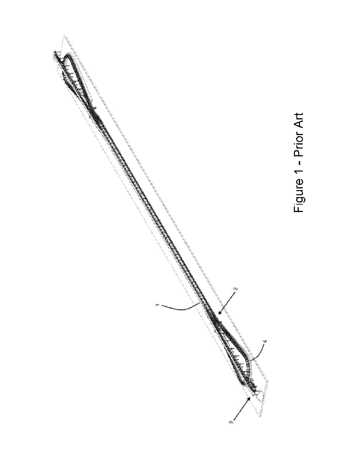
[0057]In a long distance rail conveyor system of the type shown in FIG. 1, the delivery run 1 is typically separated from the support carriages at approximately position 2 so that bulk material conveyed on the delivery run of the carry belt may be discharged at point 3 while the carriages on their rail tracks are sent around a return loop 4 before being reunited with the carry belt in the return run at location 2. While this is suitable for situations typically over long distances, it requires a wide horizontal footprint for the return loop 4 which is not always available.

[0058]While the rail conveyor technology is ideally suited to long distance transportation due to improved energy efficiency, the technology also has significant advantages when compared to conventional belt conveying systems for shorter conveying distances. Notably, the rail conveyor technology has the advantage of being able to negotiate smaller radius horizontal curves and where necessary convey bulk material in...


PUM


Abstract

The present invention provides a rail conveyor system of the type having a rail track (9) including a delivery run (1) extending between a loading end (5) and a discharge end (6) and a return run (12) extending from the discharge end (6) to the loading end (5), a plurality of carriages (8) spaced apart from one another and arranged to run on wheels (24) supported by the track (9), and a continuous carry belt (10) supported by the carriages (8); wherein, at least at the discharge end (6), the carriages (8) are turned around to return to the loading end (5) by being entrained around only one or more vertical turnover wheels (7) arranged such that the carriages (7) are delivered to the return run (12) beneath the delivery run (1).

Description

CROSS-REFERENCE TO RELATED APPLICATIONS[0001]This application is a U.S. National Stage of International Patent Application No. PCT / AU2015 / 000655, filed Oct. 29, 2015, which claims the benefit of Australian Patent Application No. AU2014904358, filed Oct. 30, 2014, each of which is incorporated by reference herein in its entirety.FIELD OF THE INVENTION[0002]This invention relates to a Rail Conveyor System with Vertical Carriage Return and has been devised particularly though not solely for use in situations requiring a narrow footprint at the head and / or tail end of the system.BACKGROUND OF THE INVENTION[0003]The following discussion of the prior art is intended to present the invention in an appropriate technical context and allow its advantages to be properly appreciated. Unless clearly indicated to the contrary, however, reference to any prior art in this specification should not be construed as an express or implied admission that such art is widely known or forms part of common g...

Claims


Application Information

Patent Timeline
Patent Type & Authority Patents(United States)
IPC IPC(8): B65G15/08E21F13/02B65G21/22B65G17/02
CPCB65G17/02E21F13/02B65G21/22B65G15/08
Inventor WHEELER, CRAIG ANTHONY
Owner NEWCASTE INNOVATION LTD
Why Eureka
Try Eureka