
Control surface for an aircraft

a control surface and aircraft technology, applied in aircraft control, aircraft stabilisation, aircraft components, etc., can solve the problems of aircraft stalling and dramatic increase of drag, and achieve the effect of reducing the separation of boundary layers and delay

Active Publication Date: 2019-05-07
AIRBUS OPERATIONS LTD
View PDF12 Cites 0 Cited by
  • Summary
  • Abstract
  • Description
  • Claims
  • Application Information

AI Technical Summary

Benefits of technology

The patent describes a way to reduce the distance between a control surface and the surrounding air, which can affect the performance of the control surface. This is accomplished by using a design that reduces the curvature of the exposed part of the control surface, which is exposed to airflow. This design also helps to delay and minimize the separation of the control surface from the air, regardless of the direction of movement. Overall, this improves the performance and efficiency of the control surface.

Problems solved by technology

For example, if when the angle of the wing increases relative to the airflow, significant areas of separation occurs, the drag increases dramatically, and the aircraft is said to stall.

Method used


Image

  • Control surface for an aircraft
  • Control surface for an aircraft
  • Control surface for an aircraft

Examples


Embodiment Construction

)

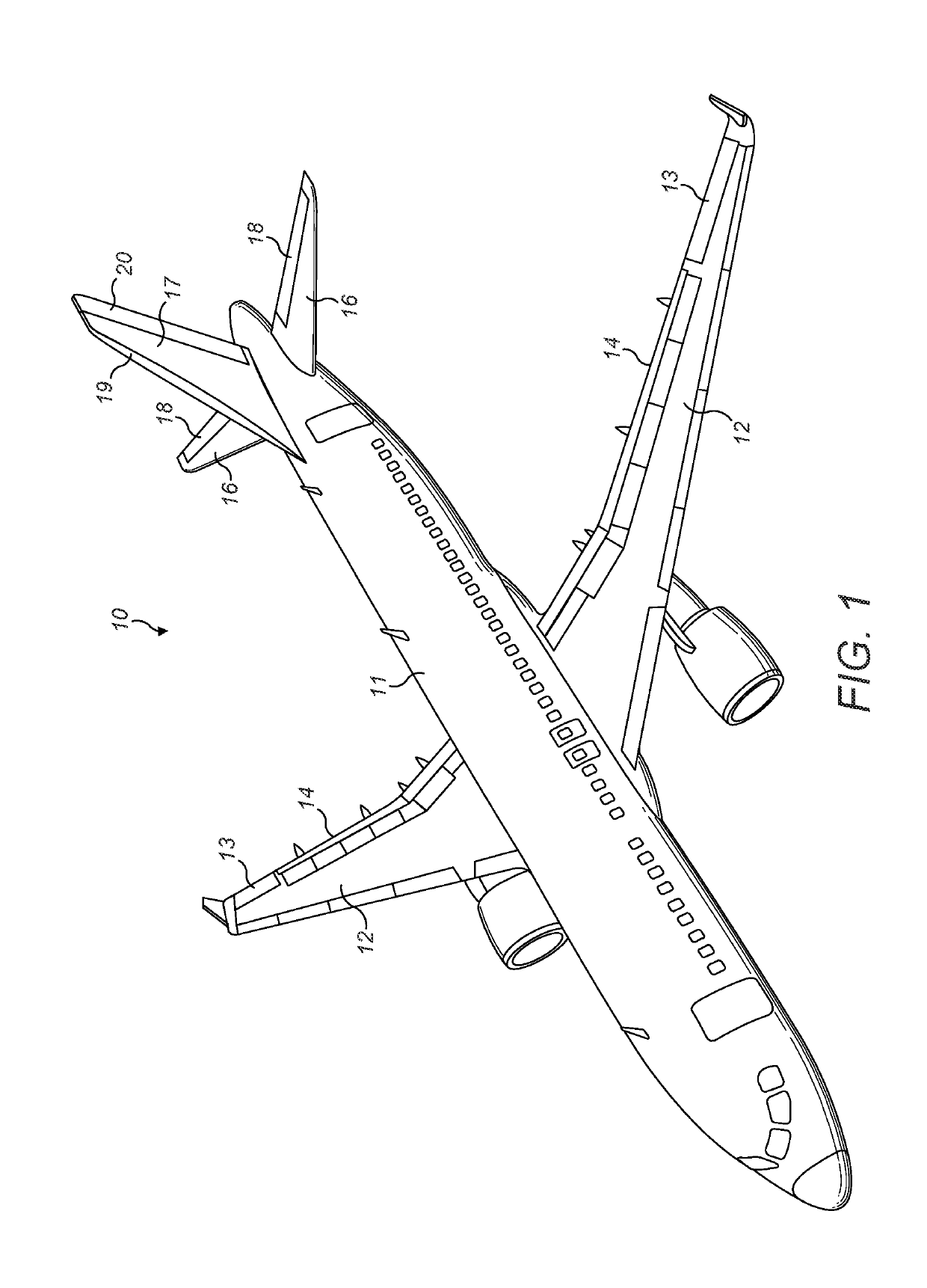
[0041]A fixed wing aircraft 10 is shown in FIG. 1. The aircraft 10 includes a fuselage 11. Two wings 12, acting as lifting surfaces, extend from the fuselage 11. It will be appreciated that lifting surfaces may take a variety of different planform shapes and profiles depending on the particular application. Each wing 12 has an aileron 13, forming a control surface, at its trailing edge 14. Proximate an aft end 15 of the aircraft 10 are two horizontal tail planes 16 and a vertical tail plane 17. Each horizontal tail plane 16 has an elevator 18, forming a control surface, at its trailing edge. The vertical tail plane 17 comprises a vertical fin 19 and a rudder 20.

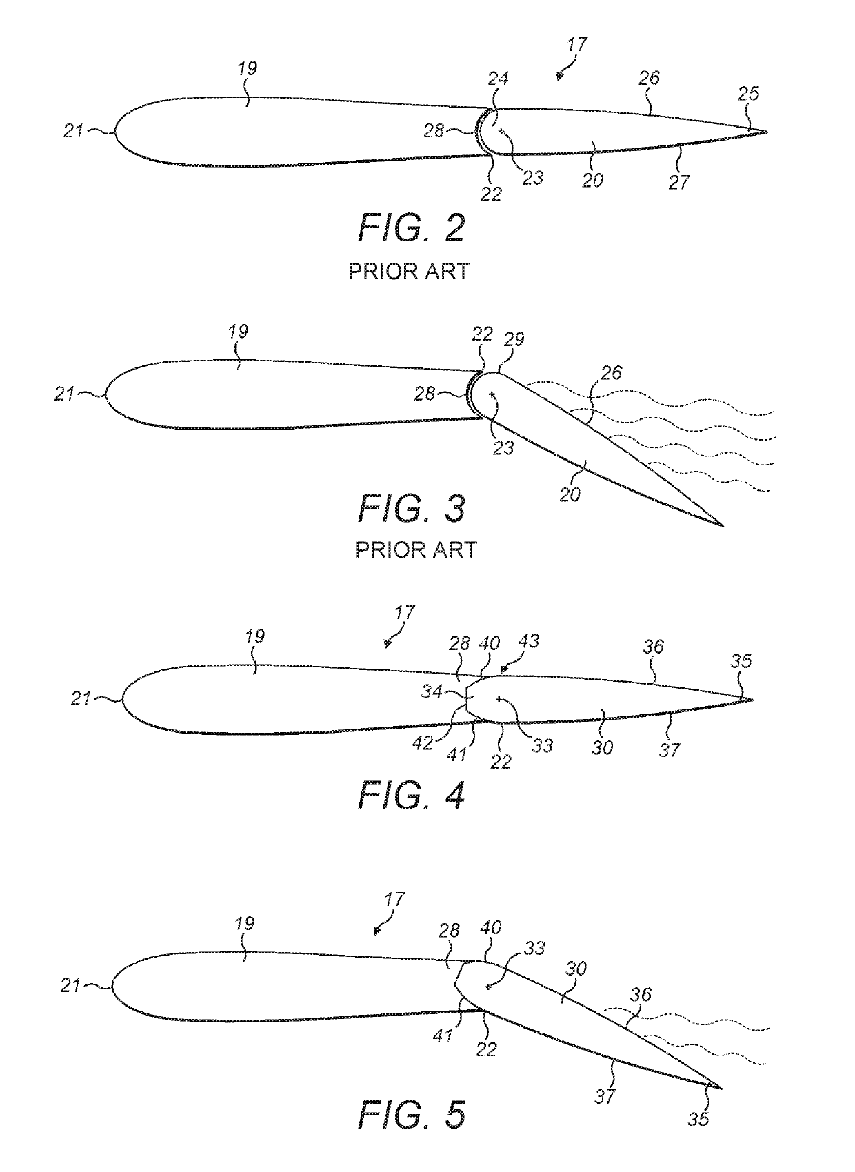
[0042]A schematic cross-sectional profile view of a known arrangement of the vertical tail plane 17 defined midway along the spanwise length of the vertical tail plane 17 is shown in FIGS. 2 and 3. The vertical fin 19 is a fixed section with a fin leading edge 21 and a boundary edge 22. At the boundary edge 22 is the rudder ...


PUM


Abstract

The present application relates to a control surface for an aircraft. The control surface has a leading edge, a trailing edge, and a chord-line defined between the leading edge and the trailing edge. A first aerodynamic surface is between the leading and trailing edges and a second surface is between the leading and trailing edges. The leading edge is formed by a nose, the nose having a hinge axis about which the control surface is deflectable. A maximum thickness of the control surface perpendicular to the chord-line between the first aerodynamic surface and the second surface is located aft of the hinge axis. The present application also relates to a control surface for an aircraft having a maximum curvature of the first aerodynamic surface of the control surface located aft of the hinge axis. The present application also relates to an aircraft or part of an aircraft comprising a fixed section and a control surface.

Description

RELATED APPLICATIONS[0001]The present application claims priority from Great Britain Application Number 1513545.2, filed Jul. 31, 2015, the disclosure of which is hereby incorporated by reference herein in its entirety.FIELD OF THE INVENTION[0002]The present invention relates to a control surface for an aircraft. The present invention also relates to an aircraft or part of an aircraft comprising a control surface.BACKGROUND OF THE INVENTION[0003]Movable control surfaces of an aircraft, such as a rudder, are generally hingably mounted to a fixed section, for example a rudder is hingably mounted to a vertical fin of a vertical tail plane. Such a movable control surface typically deflects about a hinge axis extending along the fixed section. The control surfaces generally extend from a trailing edge of a fixed surface, such as a wing or stabiliser. A conventional control surface is deflectable about their mounting.[0004]Boundary layer separation is a phenomenon shown in FIG. 3 in which...

Claims


Application Information

Patent Timeline
Patent Type & Authority Patents(United States)
IPC IPC(8): B64C9/02B64C9/18B64C9/16B64C5/06B64C9/00B64C21/00
CPCB64C9/02B64C5/06B64C9/00B64C9/18B64C9/16B64C2009/005B64C21/00B64C5/10
Inventor NORTHAM, ROBERTCHU, JAMES
Owner AIRBUS OPERATIONS LTD
Learn More