


Quick Research
Generate reliable direction feasibility study reports for your R&D in just a few steps.

Technical Q&A
Discover and master advanced knowledge NOW. Basics, ideas, possibilities, all at once.

Find Solutions
As an expert in R&D theories, this can generate solutions to your technical problems instantly.

Evaluate Feasibility
Analyze your overall solution with one click, know your potential R&D risks in advance.

Monitor Landscape
Get weekly tech updates, stay abreast of the latest tech innovations and key insights.
Bonding state inspection method
a technology of bonding state and inspection method, which is applied in the direction of manufacturing tools, instruments, non-electric welding apparatus, etc., can solve the problems of defective bonding state and poor accuracy, and achieve the effect of determining the quality of bonding sta
- Summary
- Abstract
- Description
- Claims
- Application Information
AI Technical Summary
Benefits of technology
Problems solved by technology
Method used
Image

Examples
first embodiment
Inspection Apparatus Applying a Bonding State Inspection Method
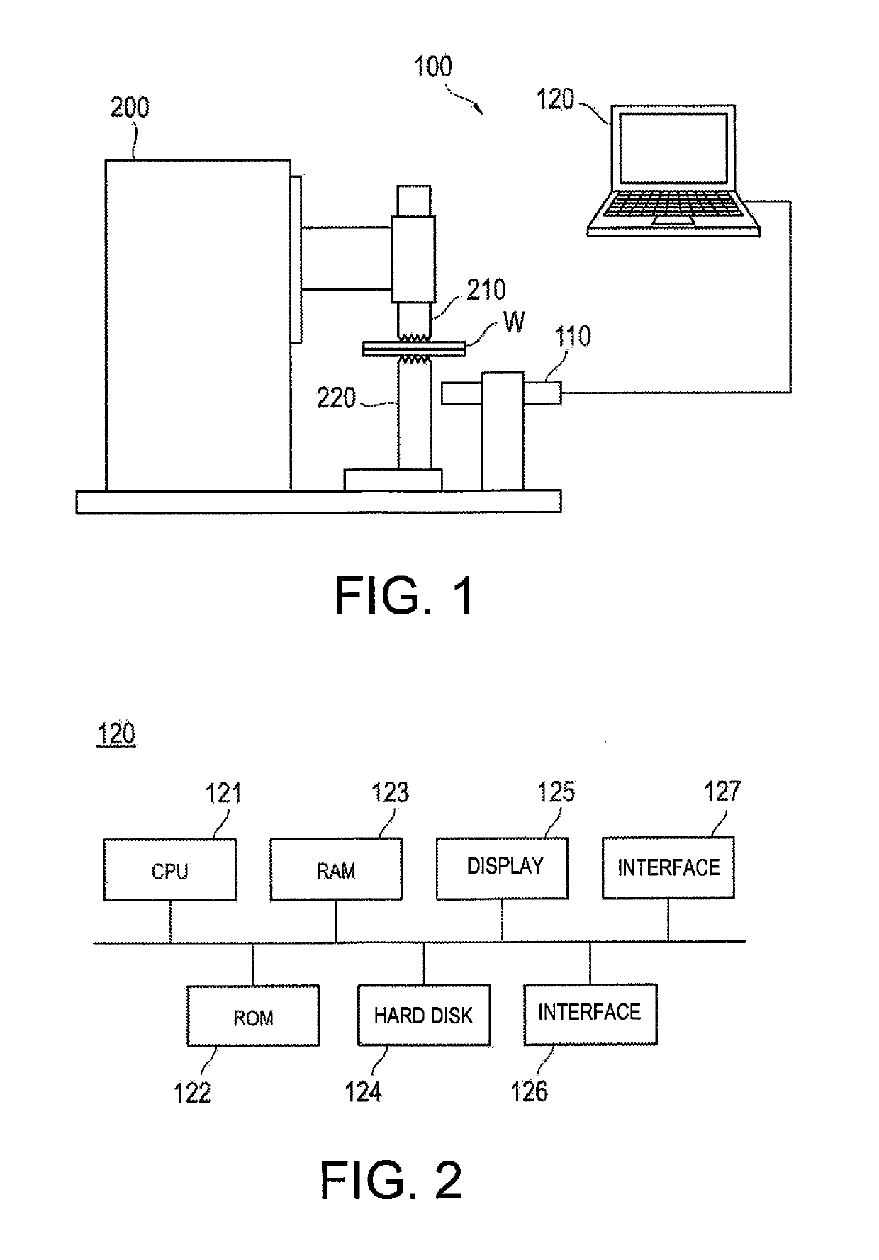
[0029]FIG. 1 is a diagram showing a schematic configuration of an inspection apparatus 100 to which the bonding state inspection method in the first embodiment is applied.
[0030]An inspection apparatus 100 inspects the bonding state of the plate material W to be ultrasonically bonded by an ultrasonic bonding apparatus 200. The ultrasonic bonding apparatus 200 includes a horn 210 to impart vibrations while pressing the sheet material W, and an anvil 220 on which the sheet material W is placed. At the tip of the horn 210 and the tip of the anvil 220 which is disposed opposite on the ultrasonic bonding apparatus 200, a plurality of protrusions having a pyramid shape are formed in a grid pattern.
[0031]The inspection apparatus 100, as shown in FIG. 1, includes a vibration sensor 110 for measuring the vibration amplitude of the anvil 220 of the ultrasonic bonding apparatus 200, and an analysis device 120 that determines the qua...
second embodiment
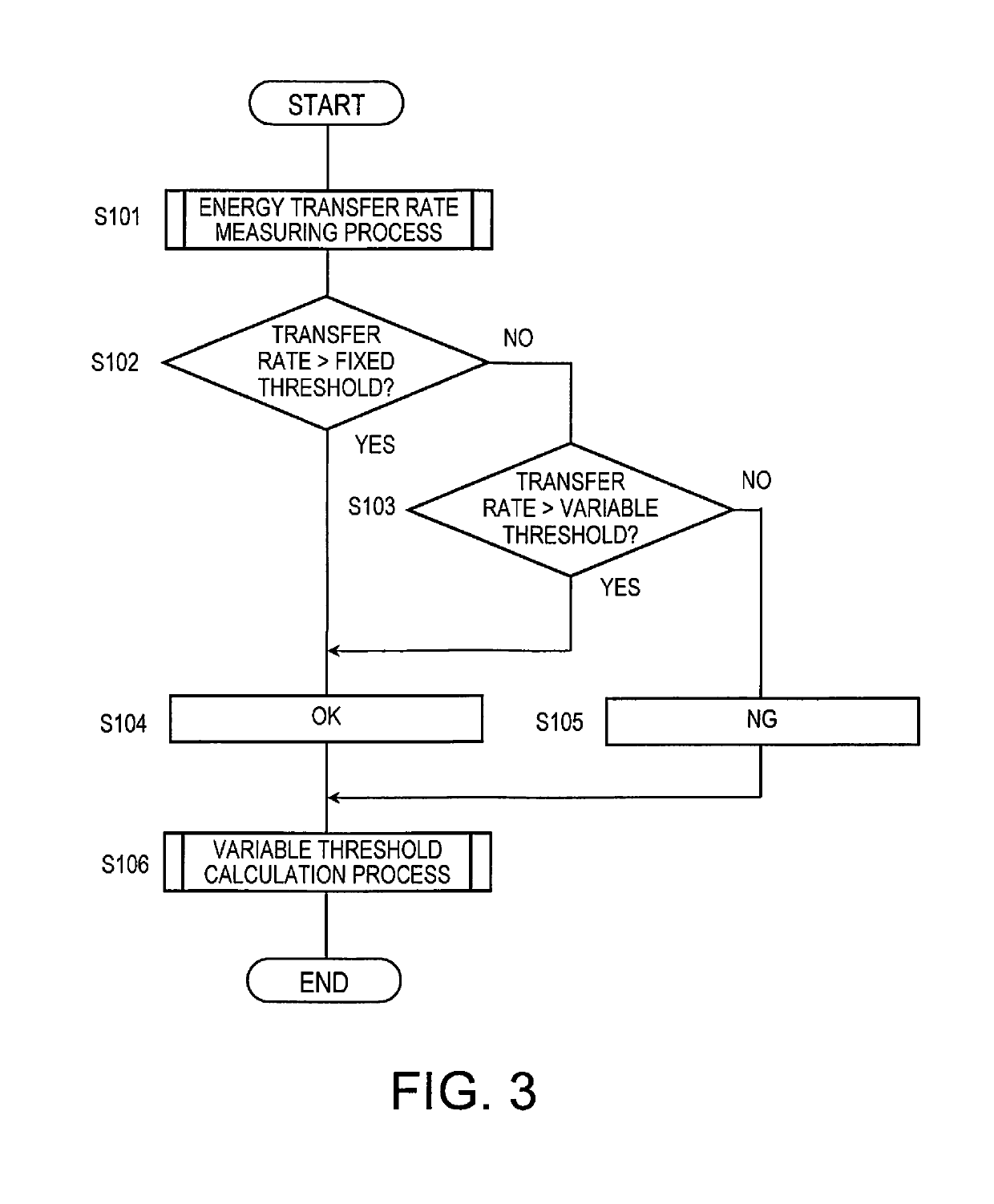
[0073]In the first embodiment described above, when the energy transfer rate to the anvil 220 does not exceed the fixed threshold, by comparing the energy transfer rate and the variable threshold, the quality of the bonding state is determined. In a second embodiment, the bonding number of ultrasonic bonding is counted. When the count does not exceed a predetermined number of times, the transfer rate is compared to a fixed threshold, whereas, when the bonding number exceeds the predetermined number, the transmission rate is compared to the variable threshold to determine the quality of the bonding state.
[0074]The inspection apparatus to which the bonding state inspection method pertaining to the second embodiment is applied may be similar to the inspection apparatus 100 to which the bonding state inspection method pertaining to the first embodiment. Below, a description will be given in detail of the bonding state inspection method pertaining to the second embodiment.
[0075]FIG. 15 i...
PUM
| Property | Measurement | Unit |
|---|---|---|
| Frequency | aaaaa | aaaaa |
| Energy | aaaaa | aaaaa |
Abstract
Description
Claims
Application Information
 - R&D Engineer
- R&D Manager
- IP Professional
- Industry Leading Data Capabilities
- Powerful AI technology
- Patent DNA Extraction
Browse by: Latest US Patents, China's latest patents, Technical Efficacy Thesaurus, Application Domain, Technology Topic, Popular Technical Reports.
© 2024 PatSnap. All rights reserved.Legal|Privacy policy|Modern Slavery Act Transparency Statement|Sitemap|About US| Contact US: help@patsnap.com