Blower

a blower and blower technology, applied in the direction of magnetic circuit rotating parts, magnetic circuit shape/form/construction, liquid fuel engines, etc., can solve the problems of motor start-up failure, torque fluctuation, vibration and noise of the motor, etc., to reduce the cogging torque and noise.

Inactive Publication Date: 2019-04-23
JOHNSON ELECTRIC SA
View PDF13 Cites 0 Cited by
  • Summary
  • Abstract
  • Description
  • Claims
  • Application Information

AI Technical Summary

Benefits of technology

[0004]Thus, there is a desire for a blower including a motor with reduced cogging torque and lower noise.

Problems solved by technology

However, a series disadvantage of a typical single-phase motor is that the rotor of the motor can easily stop at a dead-point position, which would result in startup failure of the motor.
However, such motor configured has a very large cogging torque, which causes torque fluctuation and hence vibrations and noises of the motor.

Method used


Image

  • Blower
  • Blower
  • Blower

Examples


Embodiment Construction

[0038]It should be noted that the figures are not drawn to scale and that elements of similar structures or functions are generally represented by like reference numerals for illustrative purposes throughout the figures. It also should be noted that the figures are only intended to facilitate the description of the preferred embodiments. The figures do not illustrate every aspect of the described embodiments and do not limit the scope of the present disclosure.

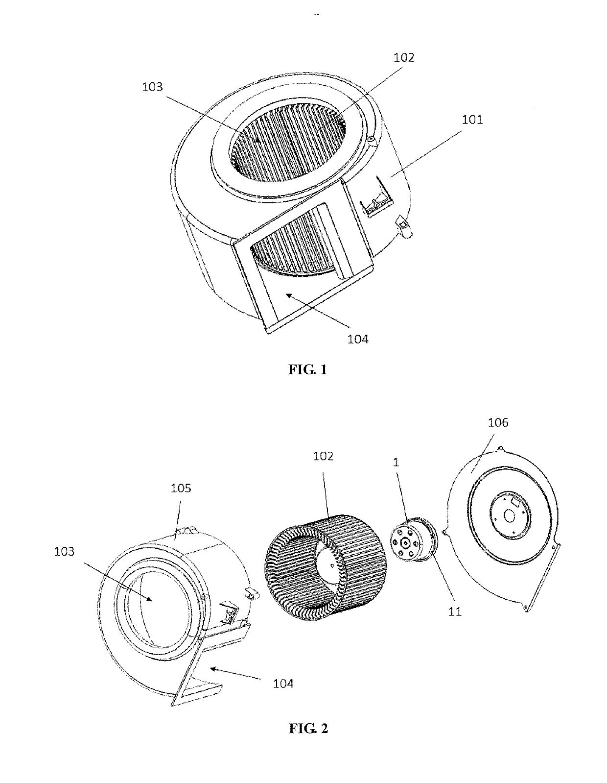
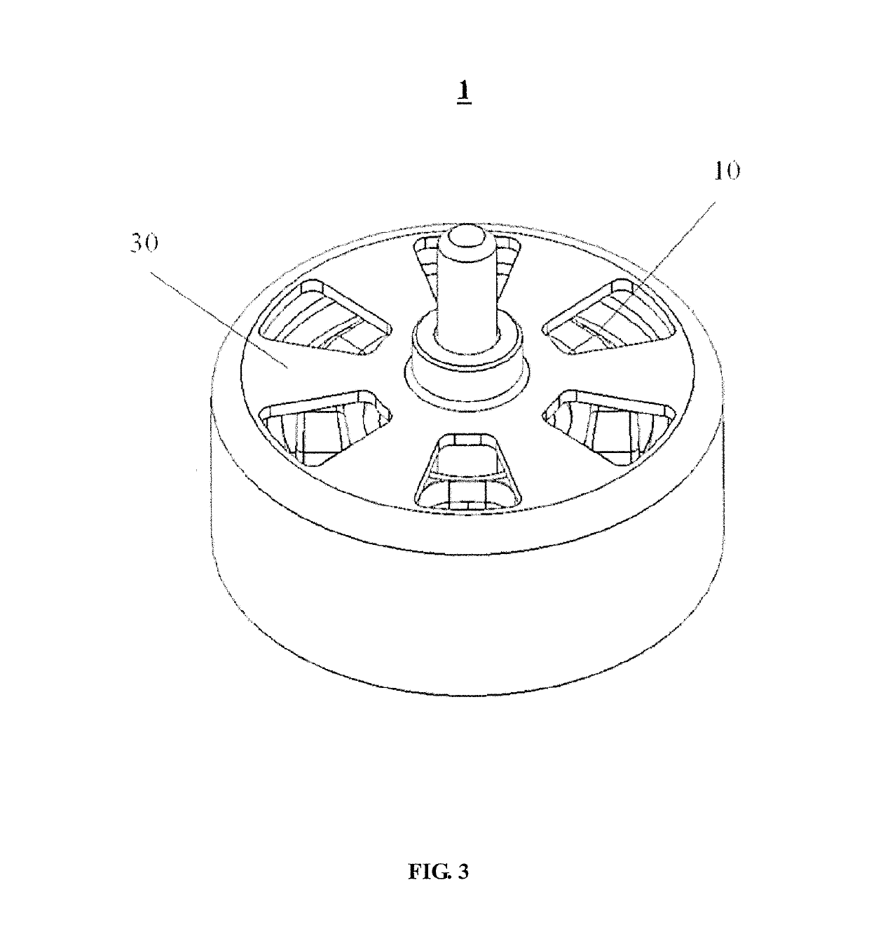
[0039]FIG. 1 and FIG. 2 illustrate a blower 100 according to one embodiment of the present invention. The blower 100 includes a housing 101, an impeller 102 received in the housing 101, and a motor 1 for driving the impeller 102. The housing 101 includes an inlet 103 and an outlet 104. The housing 101 includes an casing 105 and a cover 106. The casing 105 defines an opening at a bottom thereof, and the cover 106 is attached to the bottom of the casing 105 to cooperatively form a receiving chamber. The impeller 102 and the moto...


PUM


Abstract

A blower includes a housing, and an impeller and a motor received in the housing. The motor drives the impeller to rotate. The motor includes a stator and a rotor. The stator includes a stator core and windings wound around the stator core. The stator core includes a yoke and teeth extending from the yoke. A distal end of each of the teeth forms a tooth tip, with a slot opening formed between each two adjacent tooth tips. The rotor includes a permanent magnet forming a plurality of magnetic poles. The stator and the rotor define an air gap therebetween. A circumferential width of the slot opening is equal to or less than two times of a radial width of the air gap.

Description

CROSS REFERENCE TO RELATED APPLICATIONS[0001]This non-provisional patent application claims priority under 35 U.S.C. § 119(a) from Patent Application No. 201610077600.7 filed in The People's Republic of China on 3 Feb. 2016.FIELD OF THE INVENTION[0002]This invention relates to a ventilation device, and in particular to a blower.BACKGROUND OF THE INVENTION[0003]Blowers are commonly used air delivery devices which usually includes a motor to drive an impeller connected to the motor. The impeller in turn drives the air to generate an airflow. The motor generally includes a stator and a rotor rotatable about the stator. The rotor is connected to the impeller and hence drives the impeller to rotate to thereby drive the airflow. In order to reduce cost, single-phase motors have been used to drive the blower. However, a series disadvantage of a typical single-phase motor is that the rotor of the motor can easily stop at a dead-point position, which would result in startup failure of the mo...

Claims


Application Information

Patent Timeline
Patent Type & Authority Patents(United States)
IPC IPC(8): H02K21/12F04D25/06H02K1/27F04D17/16H02K1/14F04D29/66F04D25/08H02K29/03H02K15/095
CPCF04D17/16F04D25/0646F04D25/082F04D29/668H02K1/146H02K1/148H02K1/2786H02K15/095H02K29/03H02K2213/03H02K2213/09H02K1/12H02K1/2733H02K2201/03H02K1/2788F04D29/663F04D29/5806
Inventor CHU, JUN JIEZHANG, FU PINGZHI, YAN FANG
Owner JOHNSON ELECTRIC SA
Why Eureka
Try Eureka