
Aspirator and method of fabricating

a technology of aspirators and manufacturing methods, applied in the field of aspirators, can solve the problems of complex current aspirators, physical limitations affecting airflow through the aspirator, and high cost of aspirators, and achieve the effects of reducing the cost of machining complex parts, reducing the cost of manufacturing, and eliminating high-temperature assembly of individual parts

Active Publication Date: 2019-04-16
CIRCOR AEROSPACE
View PDF14 Cites 4 Cited by
  • Summary
  • Abstract
  • Description
  • Claims
  • Application Information

AI Technical Summary

Benefits of technology

[0010]An advantage of the present invention is that the aspirator can be fabricated inexpensively by 3-D printing. Expensive machining of complex parts can be eliminated. Because all of the features of the aspirator can be made integral as part of the printing process, high temperature assembly of the individual parts can be eliminated.
[0011]Another advantage of the present invention is that 3-D printing of the aspirator permits features to be formed in the aspirator that would be very difficult, if not impossible, to assemble using the prior art machining and brazing or welding techniques currently used to fabricate aspirators.
[0012]Still another advantage of the present invention is that the features that may be formed in the aspirator that could not otherwise be fabricated into current aspirators in a cost-effective manner, if at all, improve laminar flow of both high pressure gas and aspirated air through the aspirator.
[0013]Another advantage of the present invention, a corollary advantage to the improved laminar flow of gases through the aspirator, is that for a preselected volume of high pressure gas at a preselected pressure, an inflatable device of a preselected size may be filled more quickly with an aspirator of the present invention than with a prior art aspirator. Alternatively, an inflatable device of a preselected size may be filled as quickly with an aspirator of the present invention as a prior art aspirator, but the aspirator of the present invention will require less high pressure gas. Thus, the present invention will allow inflation of an inflatable device with less required high pressure gas or in the alternative, will inflate an inflatable device more quickly with the same volume of high pressure gas.

Problems solved by technology

The construction of current aspirators is complicated, making the aspirators expensive.
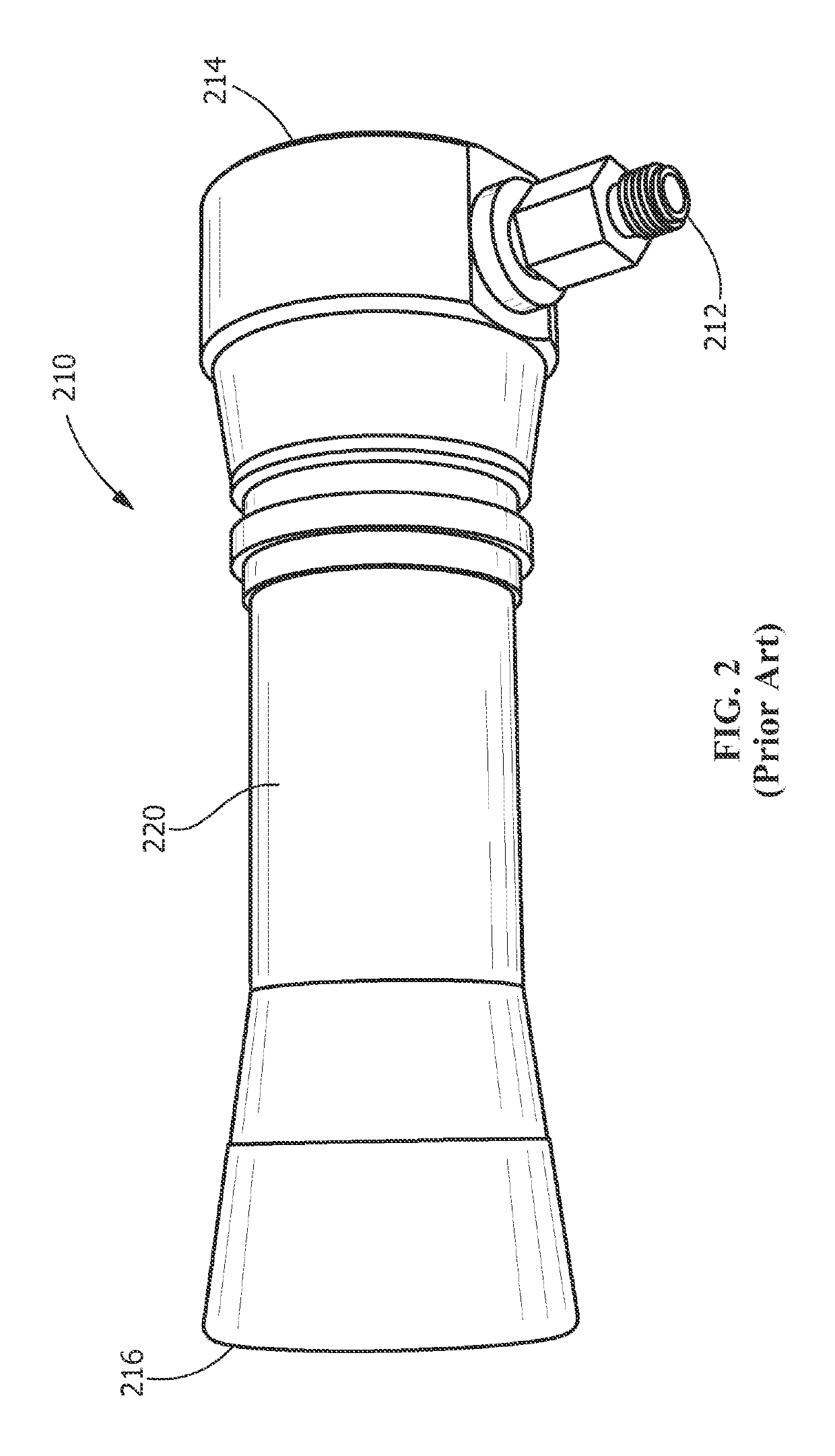
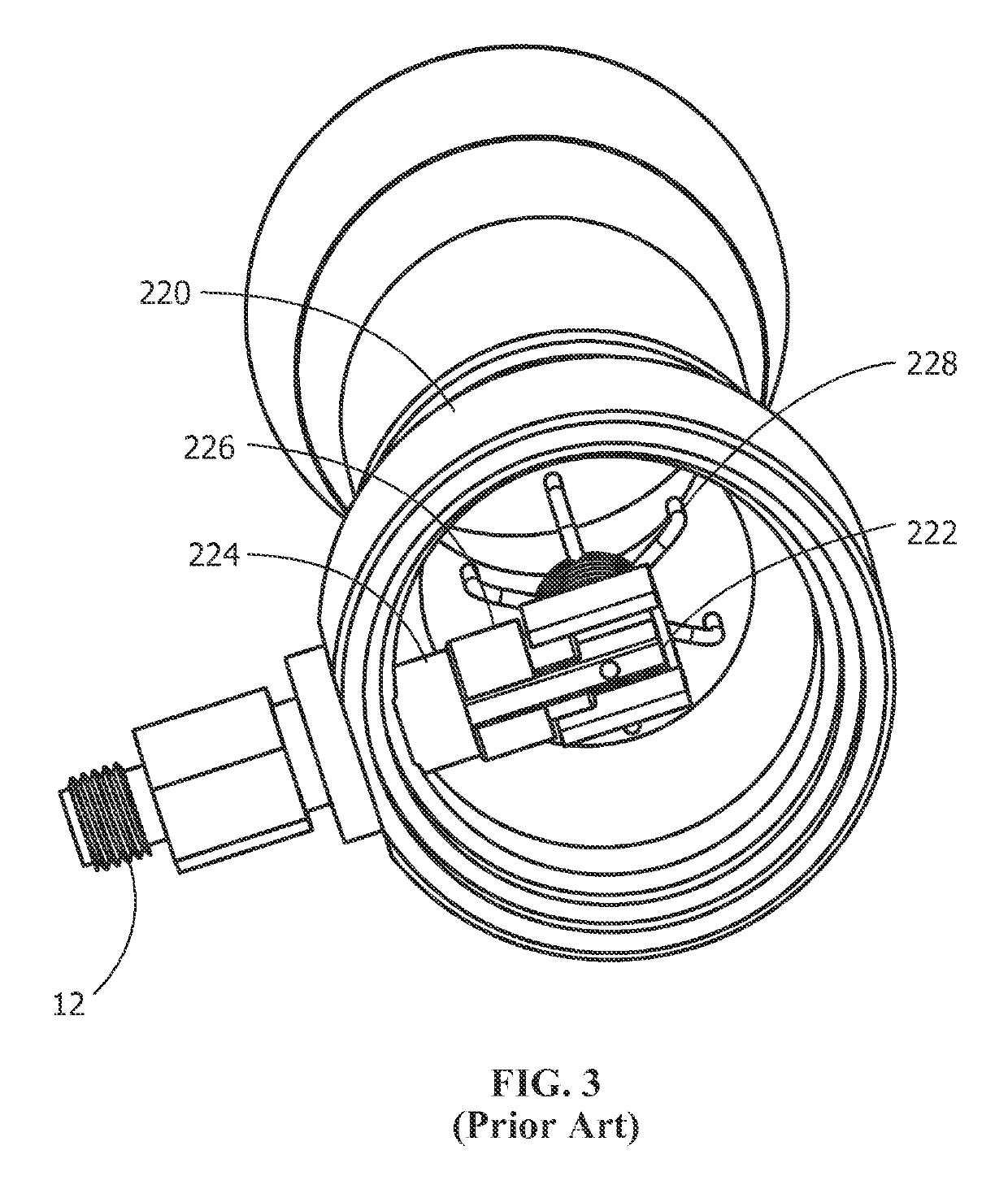
The construction also results in physical limitations that affect airflow through the aspirator. FIGS. 2-4 depict a prior art aspirator and its construction.

Method used


Image

  • Aspirator and method of fabricating
  • Aspirator and method of fabricating
  • Aspirator and method of fabricating

Examples


Embodiment Construction

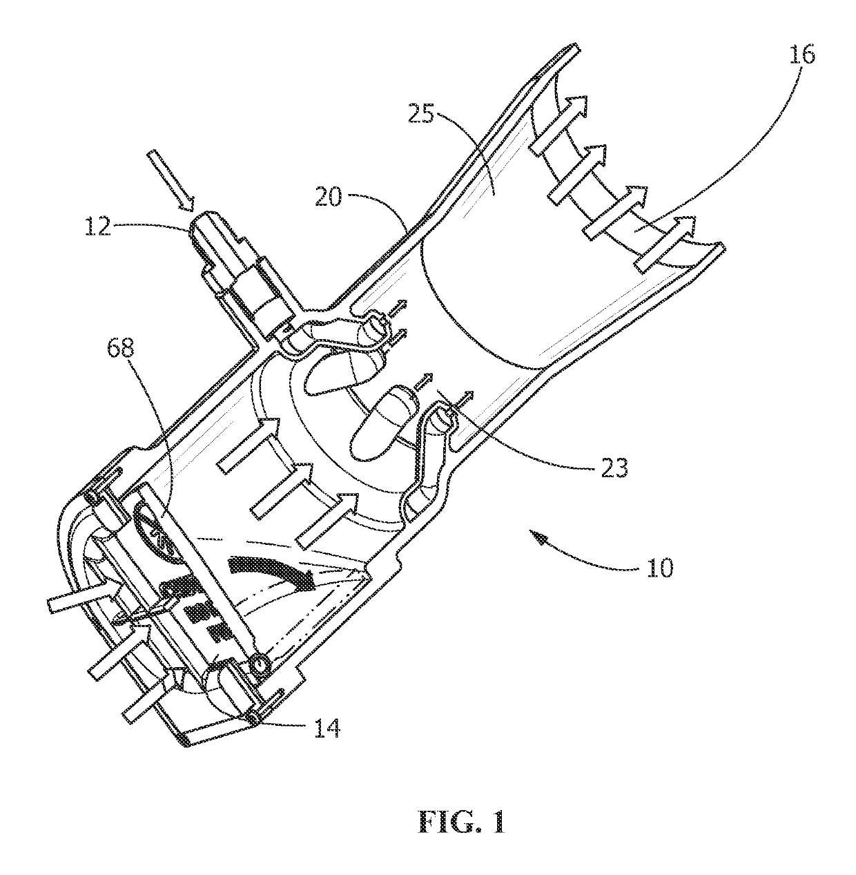
[0023]An aspirator fabricated in accordance with additive manufacturing techniques such as 3-D printing technology is set forth. The aspirator 10 generally functions as depicted in FIG. 1. The aspirator comprises an exhaust port 16 coupled to an aspirator body 20 and has a longitudinal centerline extending from a first end to a second end. High pressure compressed gas is injected into aspirator 10 through a high pressure inlet fitting 12. The high pressure gas moves through a convergent portion 23 of the aspirator 10 where the velocity of the high pressure gas increases. The velocity increase is accompanied by a pressure decrease. As a result of the pressure decrease, air at atmospheric pressure is drawn into aspirator through aspiration port 14 which is open to the atmosphere. As the gas and air mix and the mixture passes through the optional divergent portion 25, the velocity of the fluid decreases and the pressure increases as it is discharged through exhaust port 16 which is pos...


PUM

PropertyMeasurementUnit
thicknessaaaaaaaaaa
thicknessesaaaaaaaaaa
pressureaaaaaaaaaa

Abstract

An aspirator with an aspirator body and an exhaust port coupled to the body, and having a plurality of integral high pressure gas nozzles positioned along the aspirator body the body. The aspirator body includes a high pressure integral conduit in communication with a nozzle array having a plurality of high pressure gas nozzles. The nozzles are arcuate, extending away from the body toward an aspirator centerline, the nozzles extending from the aspirator body at a preselected angle toward the centerline in a direction from an atmospheric air aspiration port toward the exhaust port. A high pressure inlet port integral with the body is in communication with the conduit and a high pressure gas source. The gas may be input into the inlet port using a high pressure inlet fitting, which may be threaded onto the inlet port outside the aspirator body. The aspirator is fabricated by additive manufacturing techniques.

Description

FIELD OF THE INVENTION[0001]The present invention is directed to aspirators, and more particularly to aspirators used to inflate inflatable devices such as aircraft emergency slides, life rafts and other inflatable devices and methods of fabricating such aspirators.BACKGROUND OF THE INVENTION[0002]Aspirators are used for inflating emergency devices such as aircraft emergency slides and life rafts as well as simple floatation devices. These devices are quickly inflated with aspirators utilizing the Venturi effect with a pressurized gas, usually air, to quickly inflate a device.[0003]An aspirator is a type of ejector-jet pump that produces a vacuum by means of the Venturi effect. The fluid, a compressed gas, flows through a tube which then narrows. When the tube narrows, the fluid's speed increases, and because of the Venturi effect, its pressure decreases. The velocity energy creates a low pressure zone that can draw in and entrain a suction fluid, which may be air at atmospheric pre...

Claims


Application Information

Patent Timeline
Patent Type & Authority Patents(United States)
IPC IPC(8): F04F5/18B33Y10/00B22F7/06B33Y80/00B22F5/10F04F5/20B22F3/105F04F5/46
CPCF04F5/18B22F3/1055B22F5/106B22F7/06B33Y10/00F04F5/20F04F5/466B33Y80/00Y02P10/295F05B2230/31F05B2230/60F05B2260/601Y02P10/25B22F10/18B22F12/53B22F10/28
Inventor GASS, DAVID W.SEIBERT, ROBERT S.HICKEY, BRIAN J.LOVASCO, CHRISTOPHER R.SIRVIS, RUSSELL S.LENARDI, ROBERT CHARLES
Owner CIRCOR AEROSPACE
Learn More