Automatic air-sampling and pneumatic transport system with ball-filter hopper and integrated sampling manifold

a pneumatic transport system and air sampling technology, applied in the field of air sampling, can solve the problems of difficult and costly maintenance, limited use of air sampling devices that can analyze samples autonomously, and high cost of automated pcr/aerosol sampling machines, etc., and achieve the effect of limiting the scope of the claimed invention

Active Publication Date: 2019-04-09
DAVID BRIAN J
View PDF17 Cites 0 Cited by
  • Summary
  • Abstract
  • Description
  • Claims
  • Application Information

AI Technical Summary

Problems solved by technology

The utility of air-sampling devices that can analyze samples autonomously is often constrained by costly and delicate instrumentation needed for specialized analysis of the air samples.
For example, coupling a Polymerase Chain Reaction (“PCR”) device to an air-sampling device would allow many aerosols to be identified at the DNA level, but would require a significant investment.
Automated PCR / Aerosol Sampling machines cost up to several hundred thousand dollars, are difficult and costly to maintain properly, and may not be cost effective given the high maintenance cost in the field.
The DHS program subsequently was canceled due to high costs, false positive results, and frequently required maintenance.
Despite the benefits provided by the prior art systems, they nevertheless fall short of providing a system that eliminates the necessity for an operator to be present at the sampling site, either for the loading of individual air-sampling cartridges, the retrieval of individual used air-sampling cartridges at the end of operation, or for the retrieval of individual used air-sampling cartridges during continued operation.
Additionally, prior art systems fall short of providing a system where used air-sampling cartridges can be rapidly retrieved from an air-sampling system while the system continues to operate uninterrupted.

Method used


Image

  • Automatic air-sampling and pneumatic transport system with ball-filter hopper and integrated sampling manifold
  • Automatic air-sampling and pneumatic transport system with ball-filter hopper and integrated sampling manifold
  • Automatic air-sampling and pneumatic transport system with ball-filter hopper and integrated sampling manifold

Examples


Embodiment Construction

[0042]Embodiments of the present invention now may be described more fully hereinafter with reference to the accompanying drawings, in which some, but not all, embodiments of the invention are shown. Indeed, the invention may be embodied in many different forms and should not be construed as limited to the embodiments set forth herein. Like numbers refer to like elements throughout.

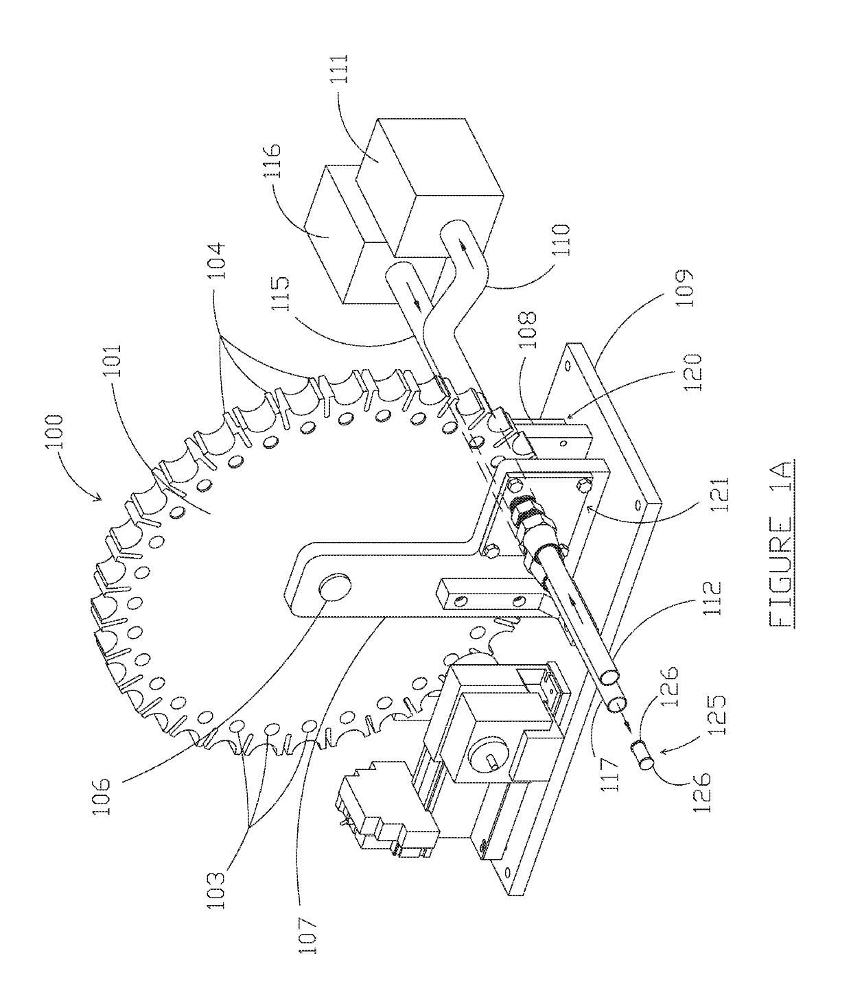
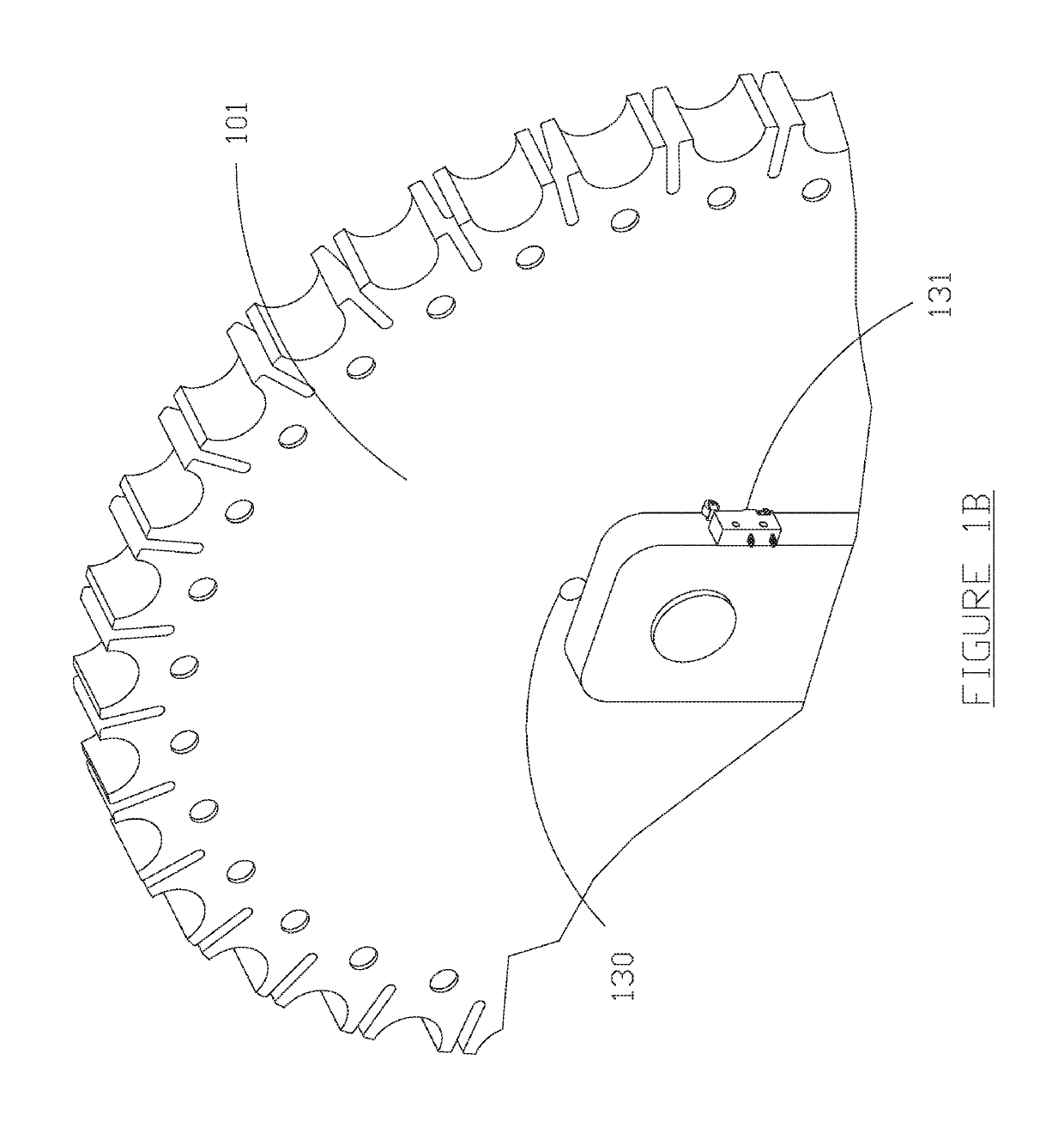
[0043]FIG. 1A is a perspective view of one embodiment of an automatic re-loading air-sampling and pneumatic transport system constructed in accordance with the teachings of the present invention with a view of a front face of a wheel assembly. In FIG. 1A, an embodiment of automatic re-loading air-sampling and pneumatic transport system 100 comprises a wheel assembly 101 and contains a plurality of chambers 103 comprising transverse cylindrical spaces with differently sized openings on opposite faces of the wheel assembly. For example, wheel assembly 101 may comprise thirty-two chambers 103, each having a ...


PUM

PropertyMeasurementUnit
diameteraaaaaaaaaa
timeaaaaaaaaaa
pressureaaaaaaaaaa

Abstract

Embodiments of the invention can sample particulates, aerosols, vapors, and / or biological components of ambient air utilizing spherical air-sampling filters. Components of the embodiments may include a hopper for holding spherical air-sampling filters, an air-sampling manifold configured to deliver an air-sampling filter from the hopper to a sampling location, and an air compressor to perform an air sampling operation and to transport a used air-sampling filter away from the sampling location. Operation of some embodiments may begin by rotating a slotted drum within the air-sampling manifold to deliver an air-sampling filter from the hopper to the sampling position. Operation may continue by using the air compressor to draw air from an ambient environment through the air-sampling filter. After sampling is complete, the air compressor may be utilized to pneumatically transport the used air-sampling filter away from the sampling position to a filter retrieval location via an output tube.

Description

CROSS REFERENCE TO RELATED APPLICATIONS[0001]This application is a continuation-in-part of U.S. patent application Ser. No. 15 / 098,405, filed on Apr. 14, 2016, which is a continuation of U.S. patent application Ser. No. 14 / 466,132, now U.S. Pat. No. 9,341,547, filed on Aug. 22, 2014, which claims priority under 35 U.S.C. § 119(e) to U.S. Provisional Patent Application No. 61 / 959,659, filed on Aug. 29, 2013. This application is also a continuation-in-part of U.S. patent application Ser. No. 15 / 297,785, filed on Oct. 19, 2016, which is a continuation of U.S. patent application Ser. No. 14 / 466,132. All of these applications are hereby incorporated by reference.BACKGROUND[0002]The present invention is related to the field of air sampling. More particularly, the present invention is related to systems that automatically collect samples of air and optionally transport those samples away from a sampling site. Still more particularly, the present invention is related to methods, systems, an...

Claims


Application Information

Patent Timeline
Patent Type & Authority Patents(United States)
IPC IPC(8): B01D46/00B01D46/42G01N1/22G01N1/24G01N1/40G01N33/00G01N1/18G01N35/04
CPCG01N1/2273B01D46/0036B01D46/42G01N1/2205G01N1/24G01N1/405G01N1/4077G01N33/0036G01N33/0055B01D2273/14G01N2001/185G01N2001/2223G01N2001/4088G01N2033/0093G01N2035/0481Y02A50/25Y02A50/20
Inventor DAVID, BRIAN J.
Owner DAVID BRIAN J
Why Eureka
Try Eureka