
Speaker module

a speaker module and speaker technology, applied in the direction of transducer details, electrical transducers, electrical apparatus, etc., can solve the problems of poor performance, easy breakage of down leads, and sacrifice the size of so as to improve the sensitivity and frequency response curve, save space for the magnetic circuit system, and generate sound.

Active Publication Date: 2019-04-02
GOERTEK INC
View PDF12 Cites 1 Cited by
  • Summary
  • Abstract
  • Description
  • Claims
  • Application Information

AI Technical Summary

Benefits of technology

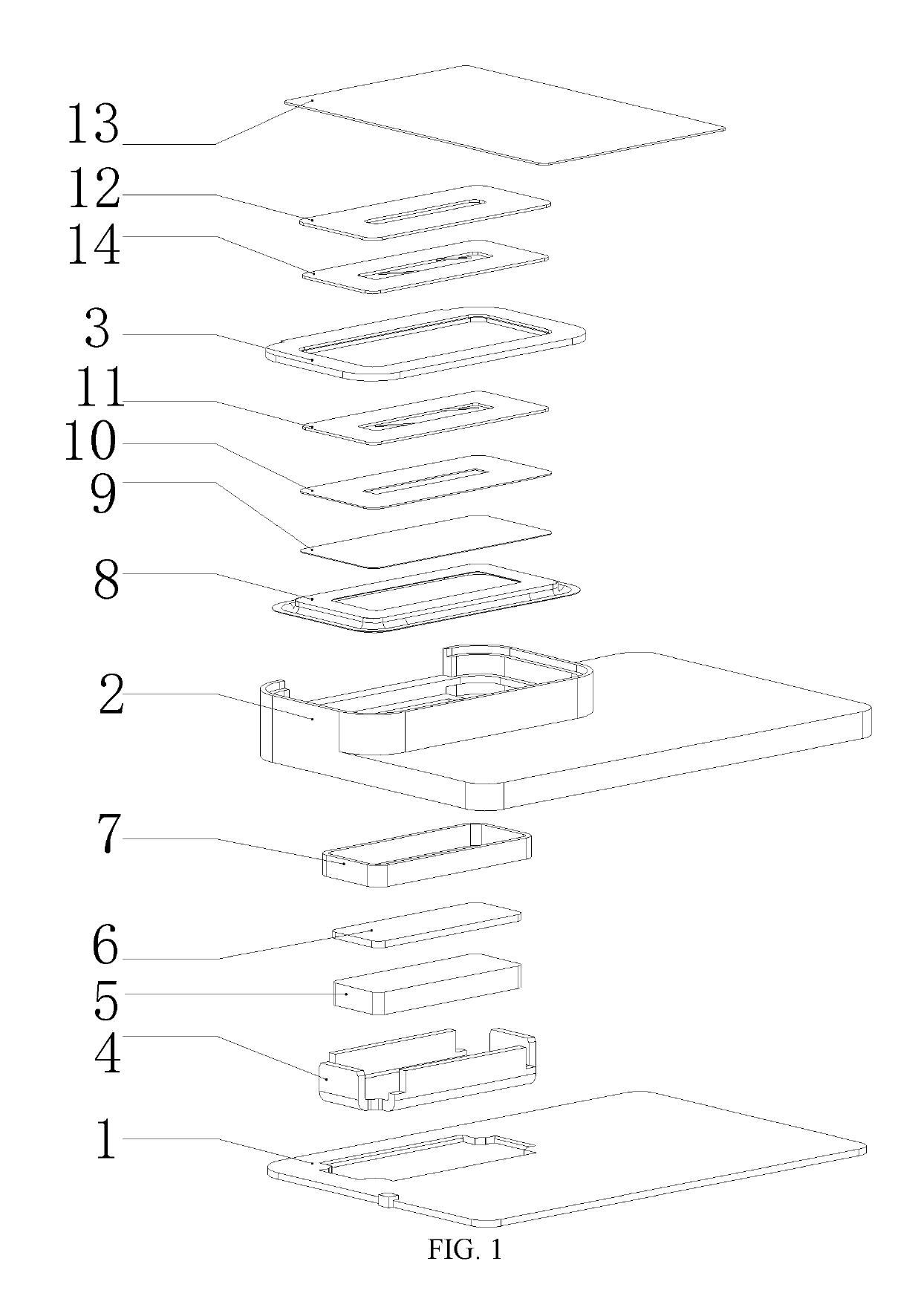
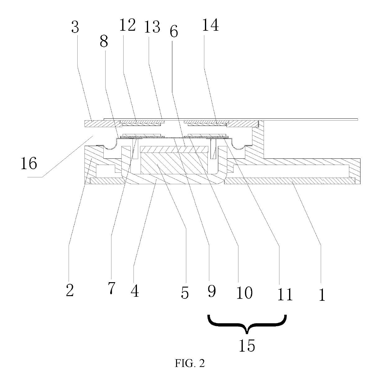
[0018]According to the speaker module of the present invention, the second induction coil is electrically connected with the terminal device, and the first induction coil is electrically connected with the voice coil. When operating, the terminal device conducts a current signal of an external audio to the second induction coil, so that the second induction coil generates a magnetic field which changes along with the change of the audio signal current. The first induction coil can induce the changing magnetic field. In other words, when the magnetic flux passing through a closed circuit changes, a changing current will be generated and is conducted to the voice coil. Then, the voice coil is driven to vibrate, and a sound generation of the speaker is achieved.
[0019]According to the speaker module of the present invention, through the first circuit board provided above the vibrating diaphragm, the first and second induction coils, the connection manner of traditional voice coil down-leads is changed, and much space is saved for the magnetic circuit system. That is, the magnetic circuit system can be made even larger to improve the sensitivity and the frequency response curve. According to the structure of the present invention, the down-leads of the voice coil are directly electrically connected with the first circuit board provided above the vibrating diaphragm and the first induction coil, so that the down-leads can vibrate along with the vibrating diaphragm. In this way, a material of the down-leads of the voice coil can be selected freely. A copper-coated aluminum down-lead or the like may be used. In addition, poor polarization caused by down-leads can be avoided. Further, in the present invention, the first circuit board provided at the upper end of the vibrating diaphragm, and the first induction coil can act as a spherical crown structure of the vibrating diaphragm, thereby improving the strength of the vibrating diaphragm at that position and changing the vibration frequency of the vibrating diaphragm.

Problems solved by technology

1. Structural makeup is required, which sacrifices the size of the magnetic circuit system; and
2. The down-leads can be easily broken, which generates an open circuit of the system to disable sound generation; and
3. Polarization will occur to the voice coil when the voice coil is vibrating due to pulling of the two down-leads, which causes poor performance.

Method used


Image

  • Speaker module
  • Speaker module

Examples


Embodiment Construction

[0025]Various exemplary embodiments of the present invention will now be described in detail with reference to the accompanying drawings. It should be noted that the relative arrangement, numerical expressions and numerical values of the components and steps set forth in these examples do not limit the scope of the invention, unless otherwise specified.

[0026]The following description of at least one exemplary embodiment is in fact merely illustrative and is in no way intended as a limitation to the present invention and its application or use.

[0027]Techniques, methods, and apparatus known to those of ordinary skill in the relevant art may not be discussed in detail but where appropriate, the techniques, methods, and apparatus should be considered as part of the description.

[0028]Among all the examples shown and discussed herein, any specific value should be construed as merely illustrative and not as a limitation. Thus, other examples of exemplary embodiments may have different valu...


PUM


Abstract

A speaker module is disclosed, which comprises an inner cavity defined by a shell, and a magnetic circuit system and a vibrating system arranged inside the inner cavity, wherein the vibrating system comprises a vibrating diaphragm fixed in the inner cavity, a voice coil is fixed to a lower end of the vibrating diaphragm, a first induction coil is provided to an upper end of the vibrating diaphragm, the voice coil is electrically connected with the first induction coil via its down-lead, and a second induction coil is provided above the first induction coil for electrically connecting a terminal device. When the speaker module operates, the terminal device conducts a current signal of an external audio to the second induction coil, so that the second induction coil generates a magnetic field which changes along with the change of the audio signal current.

Description

CROSS-REFERENCE TO RELATED APPLICATIONS[0001]This application is a National Stage Application, filed under 35 U.S.C. § 371, of International Application No. PCT / CN2015 / 097316, filed on Dec. 14, 2015, which international application claims priority to Chinese Patent Application No. 201510221328.0, filed on May 4, 2015, the contents of both of which as are hereby incorporated by reference in their entireties.BACKGROUNDRelated Field[0002]The present invention relates to the field of sound generating devices, and in particular, to a speaker module.Description of Related Art[0003]A speaker as an important acoustic component in an electronic device is a transducer for converting an electrical signal into an acoustic signal. The existing speaker module comprises a shell, and a vibrating system and a magnetic circuit system provided inside the shell. The vibrating system comprises a vibrating diaphragm and a voice coil provided on the vibrating diaphragm and used for driving the vibrating d...

Claims


Application Information

Patent Timeline
Patent Type & Authority Patents(United States)
IPC IPC(8): H04R9/00H04R9/04H04R9/02H04R9/06H04R1/02H04R1/28H04R1/22
CPCH04R1/025H04R9/025H04R9/045H04R9/046H04R9/06H04R2499/11H04R1/2865H04R2209/024H04R2209/041H04R2400/11H04R1/22
Inventor ZHANG, ZHIBINGCHEN, GANG
Owner GOERTEK INC
Learn More