Linear valve drive and valve

a technology of linear valves and valves, applied in non-electric variable control, process and machine control, instruments, etc., can solve the problem of not being able to compensate for any service life effect which occurs, and achieve the effect of simple manner

Active Publication Date: 2019-04-02
BURKERT WERKE
View PDF14 Cites 2 Cited by
  • Summary
  • Abstract
  • Description
  • Claims
  • Application Information

AI Technical Summary

Benefits of technology

[0010]The object of the present disclosure is inter alia to provide a linear valve drive and a valve which are constructed in a simple manner and by means of which an idle stroke can be adjusted.
[0012]The basic idea is to simplify the mechanical structure of the linear valve drive for the NC valve, in that the piezoelectric actuator is supported on the side of the actuating device directed towards the valve closure element. This provides a bearing for the piezoelectric actuator at the lower end of the piezoelectric actuator, i.e. on the side directed towards the valve closure element. The other end of the piezoelectric actuator is thus a free end which is displaced in a corresponding manner axially, and in particular away from the valve closure element, when the voltage of the piezoelectric actuator is changed. The actuating mechanism or actuating device can be arranged in a simple manner at this free end of the piezoelectric actuator, said mechanism or device then transmitting a pulling force to the valve closure element if the piezoelectric actuator expands. The actuating device of the linear valve drive which is required in order to transmit the force originating from the piezoelectric actuator to the valve closure element is simplified accordingly. A complicated lever effect which is provided in the actuating mechanism or actuating device and which reverses the direction of force can be omitted. The idle stroke can be adjusted in particular only once during assembly of the valve.
[0014]The adjusting device also ensures that the idle stroke can be adjusted in the actuating device, thus making it possible to react to changes in length in the actuating mechanism of the linear valve drive which are not to be prevented and which are produced e.g. by reason of service life effects or temperature effects. The idle stroke is adapted accordingly to the occurring changes in length so that they can be compensated for and have no influence upon the opening and closing behavior of the linear valve drive.

Problems solved by technology

However, it is not thereby possible to compensate for any service life effects which occur.

Method used


Image

  • Linear valve drive and valve
  • Linear valve drive and valve
  • Linear valve drive and valve

Examples


Embodiment Construction

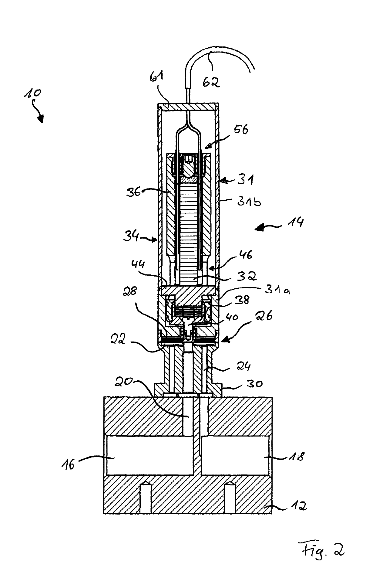
[0037]FIGS. 1 and 2 show a valve 10 used for controlling or regulating fluids. In the illustrated embodiment, the valve 10 is constructed of two parts and comprises a valve body 12 and a linear valve drive 14 which is coupled thereto.

[0038]The valve body 12 has a fluid inlet 16, via which a fluid to be controlled or regulated is supplied to the valve 10. Moreover, the valve body 12 has a fluid outlet 18, via which the fluid can exit the valve 10.

[0039]Also formed in the valve body 12 is an inflow channel 20 which is in flow communication with the fluid inlet 16. The inflow channel 20 opens into a collecting space 22 which, in turn, is in flow communication with two outflow channels 24 which open into the fluid outlet 18.

[0040]The valve body 12 is formed in particular from a rustproof material. In particular, the inner sides of the fluid-carrying channels and spaces are made of a rustproof material.

[0041]Moreover, the inflow channel 20 is allocated to a valve seat 26 (see FIG. 3), wi...


PUM


Abstract

A linear valve drive for connection to a valve body which has a valve seat is described, wherein said linear valve drive comprises a drive housing, a valve closure element and a piezoelectric actuator which is arranged within said drive housing. Said valve closure element is displaceable in the axial direction between an open position and a closed position by means of said piezoelectric actuator and an interposed actuating device. Said piezoelectric actuator is supported on said actuating device via its side directed towards the valve closure element. Said linear valve drive comprises an adjusting device which is configured such that an idle stroke of said linear valve drive is adjustable. A valve is also described.

Description

FIELD OF THE INVENTION[0001]Embodiments of the present disclosure relate to a linear valve drive for connection to a valve body, which has a valve seat, and to a valve, in particular a valve which is closed without current, i.e. a normally closed valve (NC valve).BACKGROUND OF THE INVENTION[0002]Prior art valves for controlling or regulating fluids are known, which include a valve body and a linear valve drive formed separately from the valve body. The linear valve drive and the valve body are connected to one another in order to form the valve.[0003]The linear valve drive has a drive unit, e.g. a piezoelectric actuator. The drive unit can displace a valve closure element by means of an actuating device, which is provided in the linear valve drive, or an actuating mechanism. For instance, the linear valve drive can move the valve closure element at least to an open and / or a closed position in which the valve closure element lies on a valve seat formed in the valve body and seals sai...

Claims


Application Information

Patent Timeline
Patent Type & Authority Patents(United States)
IPC IPC(8): F16K31/00G05D7/06H01L41/23H01L41/083H01L41/053
CPCF16K31/004F16K31/007F16K31/008H01L41/23G05D7/0635Y10T137/7761H01L41/053H01L41/083H10N30/02H10N30/50H10N30/88
Inventor SCHUPP, MICHAELWESTERMANN, JAN
Owner BURKERT WERKE
Why Eureka
Try Eureka