
Aircraft with internally housed propellor units

a propellor unit and internal housing technology, applied in aircrafts, vertical landing/take-off aircraft, transportation and packaging, etc., can solve the problems of low fuel/energy efficiency, loss of lift, and loss of aircra

Inactive Publication Date: 2019-04-02
RAGLAND JON M
View PDF18 Cites 25 Cited by
  • Summary
  • Abstract
  • Description
  • Claims
  • Application Information

AI Technical Summary

Problems solved by technology

Such an arrangement contributes to loss of lift.
As a result, however, there is no motor redundancy, which will lead to the loss of the aircraft should only one motor fail.
In addition, typical motor arrangements have not been optimized, resulting in low fuel / energy efficiency.

Method used


Image

  • Aircraft with internally housed propellor units
  • Aircraft with internally housed propellor units
  • Aircraft with internally housed propellor units

Examples


Embodiment Construction

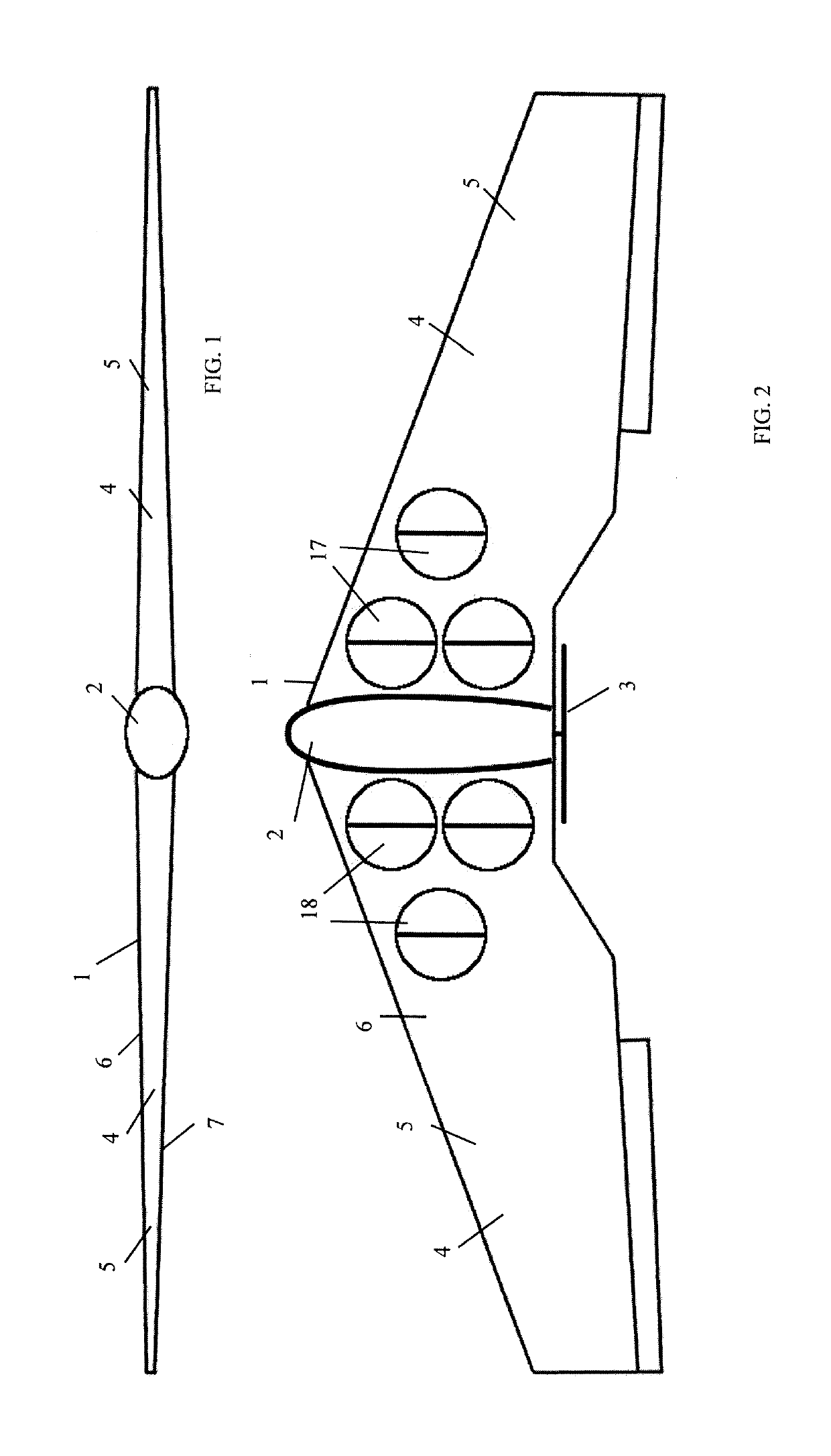
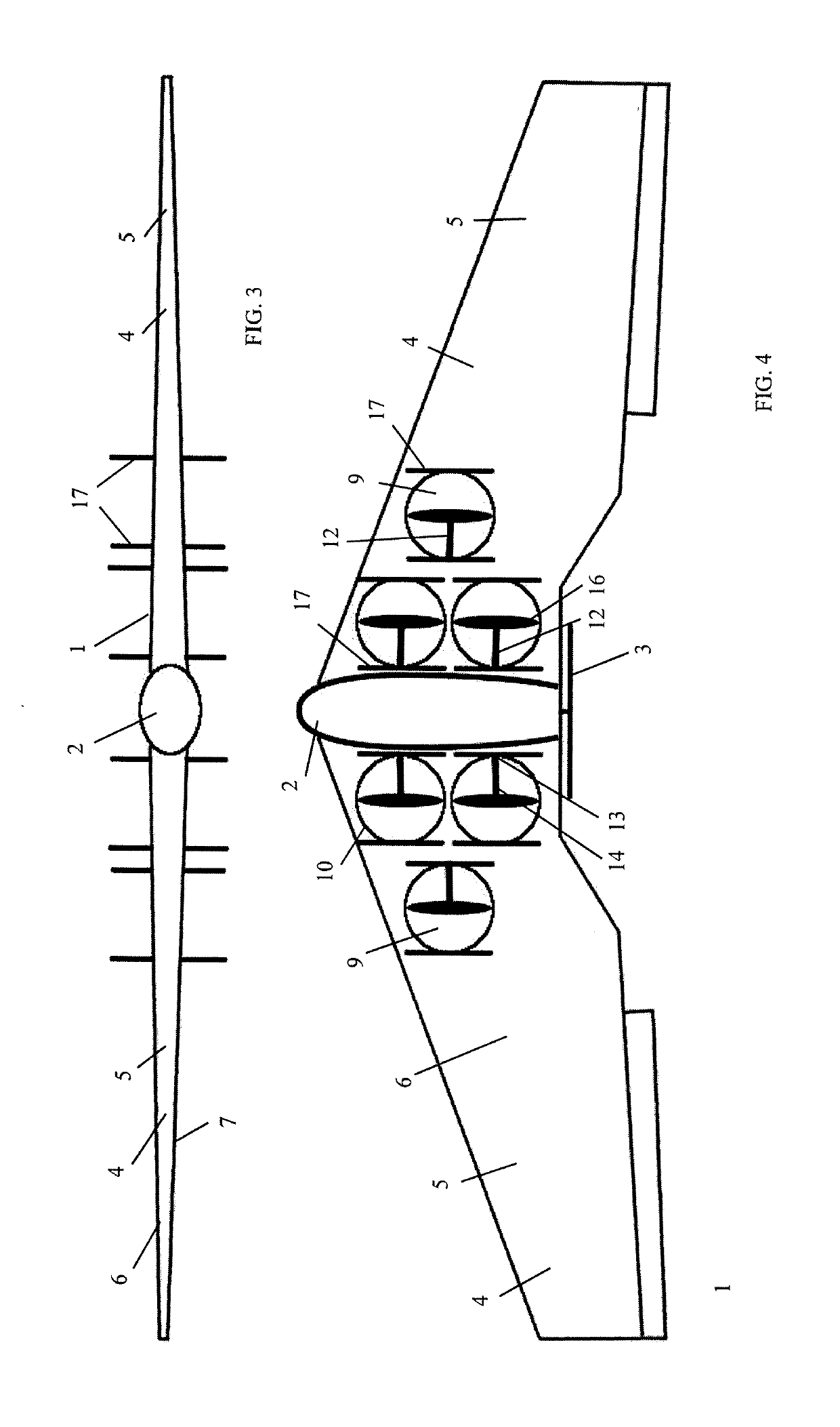
[0022]Referencing then FIGS. 1-10, shown is the instant aircraft 1. As to the body of the aircraft 1, or airframe 2, in the preferred embodiment a tail-less “flying wing” design is shown. Removing the tail offsets weight, and has the added benefit of reducing the overall size of the plane. The aircraft 1 may or may not include a fuselage, although a fuselage is shown, hence airframe 2 means the body of the aircraft 1 with or without a fuselage. The airframe 2 that is selected needs to consider the needs of the vertical thrust propellors 16 for efficient operation. The airframe 2 simply requires two sides 4, and a swept wing 5 design is preferred. By using a swept wing design, the center of gravity (CG) that is needed for the wings 5 to operate efficiently can be moved back to match the center of gravity needed by the vertical thrust propellors 16. This will allow the ducts 9 to fit within the shape of the wing 5 and have the center of gravity located appropriately, as further descri...


PUM


Abstract

A VTOL aircraft, preferably of the swept wing design. An arrangement of propellors and motors are individually housed within ducts which are mounted within a wing. Each individual motor support arm will run from the motor it is supporting, through the duct wall and into the wing and will be attached to a central frame structure housed in the fuselage. Covers are provided over the ducts, operable by motor means such as a servo. When the aircraft is relying on the internally housed propellors to provide lift, the covers will be open to allow air to pass through the ducts. When the aircraft is relying on airflow over the wings to provide lift these covers can be closed to provide uninterrupted airflow over the wings. The covers are designed to match the surface contour of the wing when closed.

Description

CROSS-REFERENCE TO RELATED APPLICATIONS[0001]The instant application claims benefit of provisional application Ser. No. 62 / 262,041, filed Dec. 2, 2015, the contents of which are incorporated herein by reference.BACKGROUND[0002]Field of the Invention[0003]The instant invention relates to tail-less, fixed wing aircraft having horizontal or vertical take-off and landing capabilities (VTOL).[0004]Description of the Related Art[0005]Aircraft incorporating helicopter-like, rotary lift propellers are known in the art. For instance, U.S. Pat. No. 6,886,776 to Wagner et al. shows a personal aircraft (PAC) capable of vertical take-off and landing (VTOL) comprising a fixed wing and a fuselage with a passenger compartment having a front, a rear and two sides, and a plurality of independently powered thrusters, preferably integrated into the wing, on each side of the fuselage. The thrusters, which are ducted fan units capable of providing a vertically upward force to the aircraft, are provided w...

Claims


Application Information

Patent Timeline
Patent Type & Authority Patents(United States)
IPC IPC(8): B64C29/00B64C39/10B64C3/32
CPCB64C29/0025B64C39/10B64C3/32Y02T50/12Y02T50/10
Inventor RAGLAND, JON M.
Owner RAGLAND JON M
Learn More