
Systems, devices, and methods for laser projectors

a laser projector and laser diode technology, applied in the field of laser projectors, can solve the problems of user's inability to see their external environment, temporary or permanent damage to the eye, and many of the aforementioned examples of wearable heads-up displays have struggled to find traction in consumer markets, so as to prevent further modulation of at least one laser diode.

Active Publication Date: 2019-03-12
GOOGLE LLC
View PDF139 Cites 3 Cited by
  • Summary
  • Abstract
  • Description
  • Claims
  • Application Information

AI Technical Summary

Benefits of technology

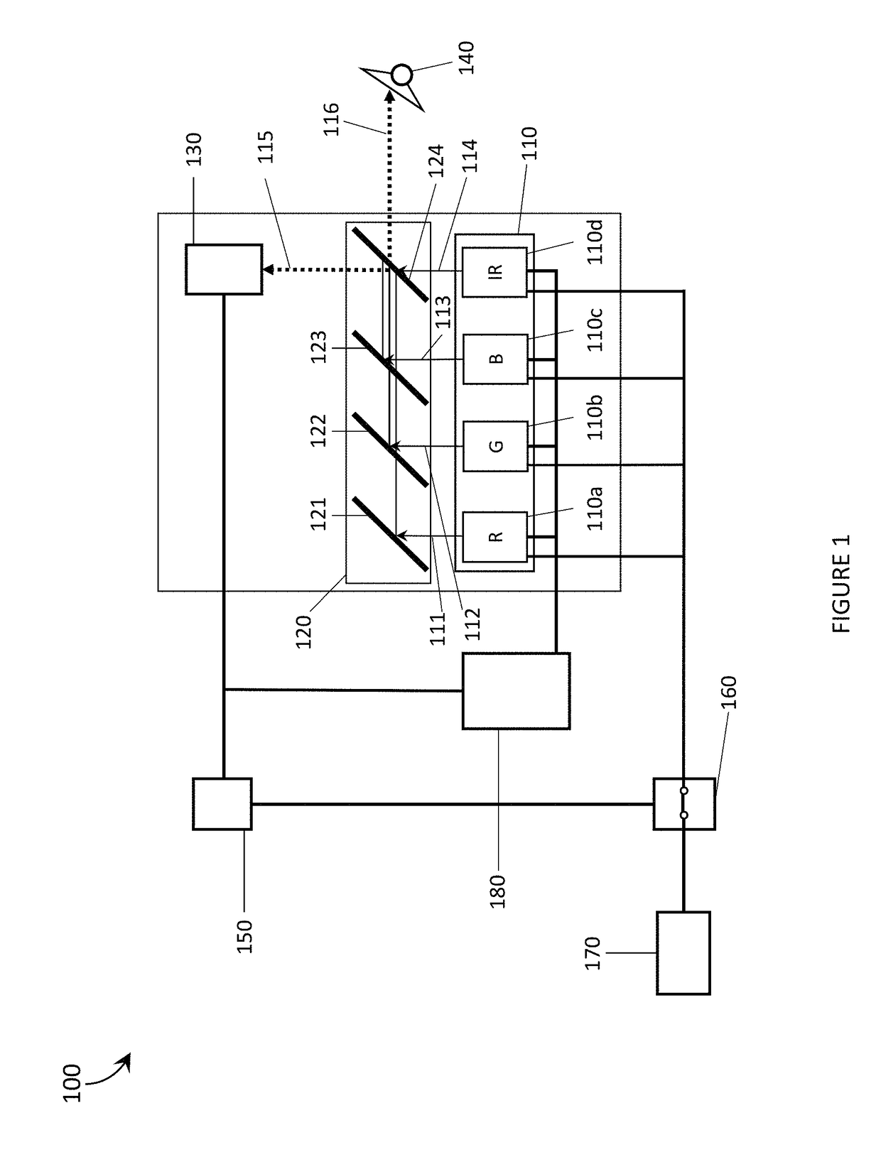
The patent text describes a laser projector that includes a processor and a photodetector. The processor modulates the laser diode to control the power of the laser light output. When the power exceeds a threshold, the processor stops modulating the laser diode to prevent further modulations. The laser projector may also include a non-transitory processor-readable storage medium that stores a flag indicating that the power exceeds the threshold. The processor accesses the storage medium upon boot-up and checks for the flag to prevent the modulation of the laser diode. The technical effect of this patent text is to improve the stability and reliability of the laser projector by preventing excessive power output and modifications to the laser diode.

Problems solved by technology

Malfunction or improper use of laser devices can result in temporary or permanent damage to the eye; therefore, laser safety precautions are essential.
A wearable heads-up display is a head-mounted display that enables the user to see displayed content but also does not prevent the user from being able to see their external environment.
Independent of their performance limitations, many of the aforementioned examples of wearable heads-up displays have struggled to find traction in consumer markets because, at least in part, they lack fashion appeal.
Most wearable heads-up displays presented to date employ large display components and, as a result, most wearable heads-up displays presented to date are considerably bulkier and less stylish than conventional eyeglass frames.
A challenge in the design of wearable heads-up displays is to minimize the bulk of the face-worn apparatus while still providing displayed content with sufficient visual quality.

Method used


Image

  • Systems, devices, and methods for laser projectors
  • Systems, devices, and methods for laser projectors
  • Systems, devices, and methods for laser projectors

Examples


Embodiment Construction

[0027]In the following description, certain specific details are set forth in order to provide a thorough understanding of various disclosed embodiments. However, one skilled in the relevant art will recognize that embodiments may be practiced without one or more of these specific details, or with other methods, components, materials, etc. In other instances, well-known structures associated with portable electronic devices and head-worn devices, have not been shown or described in detail to avoid unnecessarily obscuring descriptions of the embodiments.

[0028]Unless the context requires otherwise, throughout the specification and claims which follow, the word “comprise” and variations thereof, such as, “comprises” and “comprising” are to be construed in an open, inclusive sense, that is as “including, but not limited to.”

[0029]Reference throughout this specification to “one embodiment” or “an embodiment” means that a particular feature, structures, or characteristics may be combined ...


PUM


Abstract

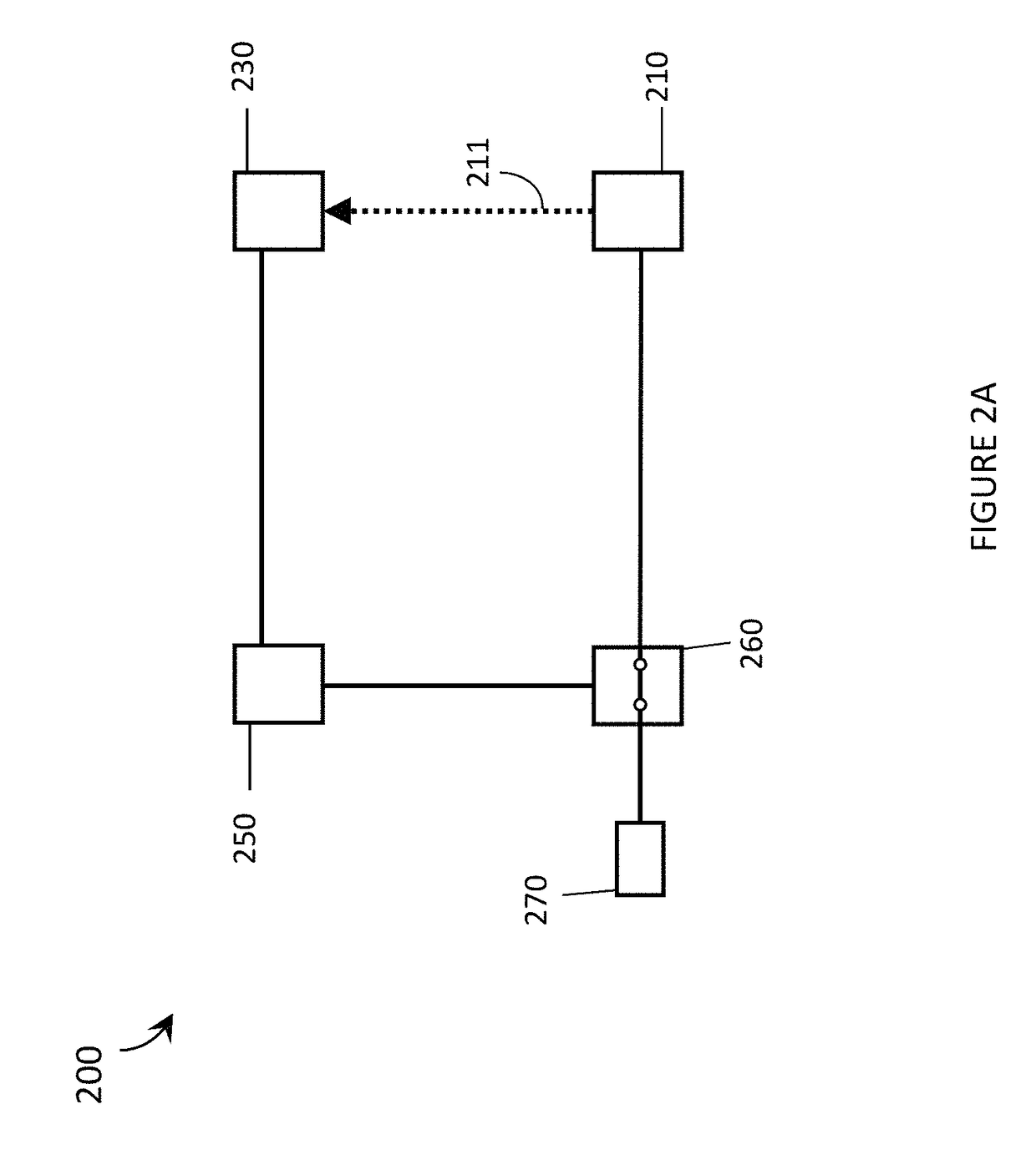
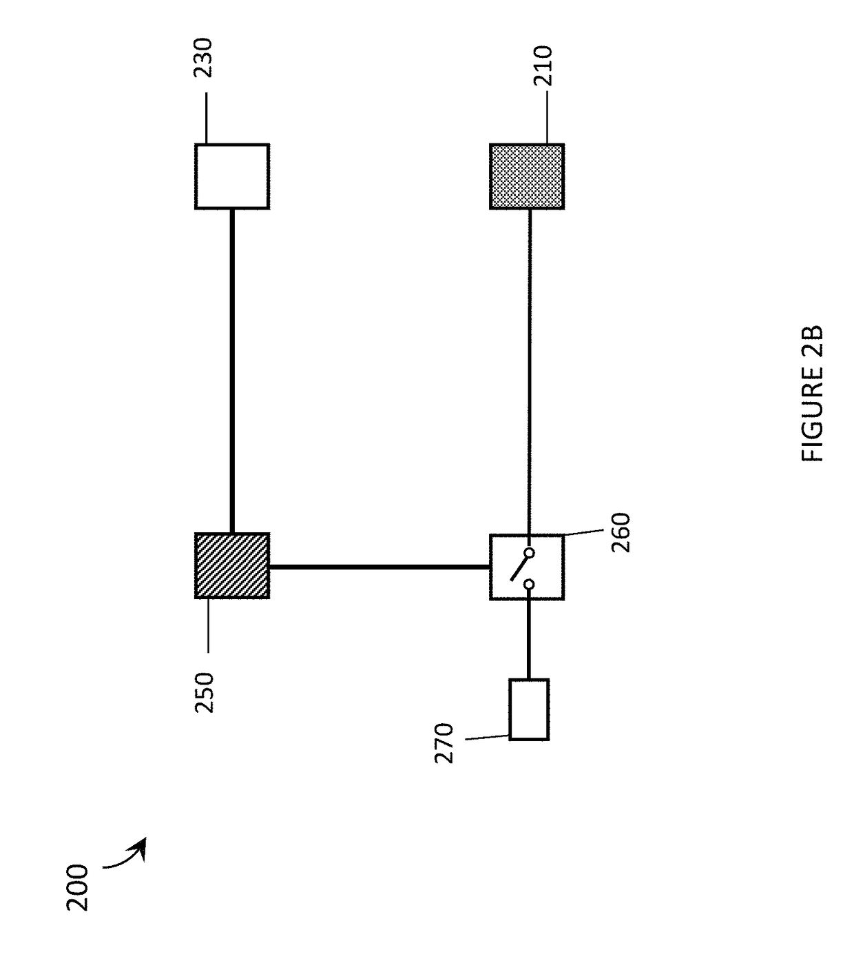
Laser safety systems, devices, and methods for use in laser projectors are described. A laser projector includes any number of laser diodes that each emit laser light, a shared laser diode power source, a photodetector to detect a power / intensity of a portion of the laser light, a beam splitter to direct a first portion of the light towards the photodetector and a second portion of the light towards an output on the projector, and a laser safety circuit responsive to signals from the photodetector. The laser safety circuit selectively electrically couples / uncouples the laser diodes from the power source depending on the power / intensity of the laser light detected by the photodetector. Particular applications of the laser safety systems, devices, and methods in a wearable heads-up display are described.

Description

TECHNICAL FIELD[0001]The present systems, devices, and methods generally relate to laser projectors and particularly relate to the safety of laser projectors.BACKGROUNDDescription of the Related ArtLaser Projectors[0002]A projector is an optical device that projects or shines a pattern of light onto another object (e.g., onto a surface of another object, such as onto a projection screen) in order to display an image or video on that other object. A projector necessarily includes a light source, and a laser projector is a projector for which the light source comprises at least one laser. The at least one laser is temporally modulated to provide a pattern of laser light and usually at least one controllable mirror is used to spatially distribute the modulated pattern of laser light over a two-dimensional area of another object. The spatial distribution of the modulated pattern of laser light produces an image at or on the other object. In conventional scanning laser projectors, the at...

Claims


Application Information

Patent Timeline
Patent Type & Authority Patents(United States)
IPC IPC(8): H04N9/31G02B27/01H01S5/068H01S5/00H01S5/40H01S5/042
CPCH04N9/3155G02B27/0172H01S5/0014H01S5/06825H04N9/3194H04N9/3161H01S5/4093G02B2027/0112G02B2027/0178H01S5/042
Inventor XU, KAI
Owner GOOGLE LLC
Learn More