
Apparatus and method to configure antenna beam width

a technology of antenna beam and antenna antenna, applied in the field of antenna beam width configuration apparatus, can solve the problem of not offering any mimo or beamforming functionality in the elevation dimension, and achieve the effect of different antenna beam width, different antenna tilt, and different beam width

Active Publication Date: 2019-01-22
FUTUREWEI TECH INC +1
View PDF15 Cites 2 Cited by
  • Summary
  • Abstract
  • Description
  • Claims
  • Application Information

AI Technical Summary

Problems solved by technology

However, the current setup of the cross-polarized antennas, with a fixed down tilt angle of the two polarized beams, does not offer any MIMO or beamforming functionality in the elevation dimension.

Method used


Image

  • Apparatus and method to configure antenna beam width
  • Apparatus and method to configure antenna beam width
  • Apparatus and method to configure antenna beam width

Examples


Embodiment Construction

[0021]The making and using of embodiments of this disclosure are discussed in detail below. It should be appreciated, however, that the concepts disclosed herein can be embodied in a wide variety of specific contexts, and that the specific embodiments discussed herein are merely illustrative and do not serve to limit the scope of the claims. Further, it should be understood that various changes, substitutions and alterations can be made herein without departing from the spirit and scope of this disclosure as defined by the appended claims.

[0022]A cross polarized antenna system that produces high-beam and low-beam transmission signals having different antenna beam down tilt angles and different polarizations is discussed in U.S. patent application Ser. No. 14 / 609,251 filed Jan. 29, 2015 and entitled “Apparatus and Methods for Cross-Polarized Tilt Antennas,” which is incorporated by reference herein as if reproduced in its entirety.

[0023]Aspects of this disclosure expand on that conce...


PUM


Abstract

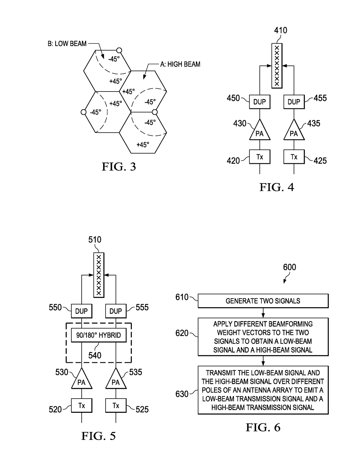
Using High-beam and low-beam transmission signals that have different antenna tilts, different beam-widths, and different polarizations than one another may provide performance advantages in wireless networks. The high-beam transmission signal and the low-beam transmission signal may have orthogonal polarizations. For example, the high-beam transmission signal and the low-beam transmission signal may be linearly polarized signals having different electromagnetic field (E-field) polarization angles with respect to the y-axis, e.g., + / − forty-five degrees with respect to a vertically polarized wave. As another example, the high-beam transmission signal may be a vertically polarized signal, and the low-beam transmission signal may be a horizontally polarized signal, or vice-versa. In addition to having orthogonal polarizations, the low-beam transmission signal may have a greater antenna beam down-tilt angle, and a wider beam-width than the high-beam transmission signal.

Description

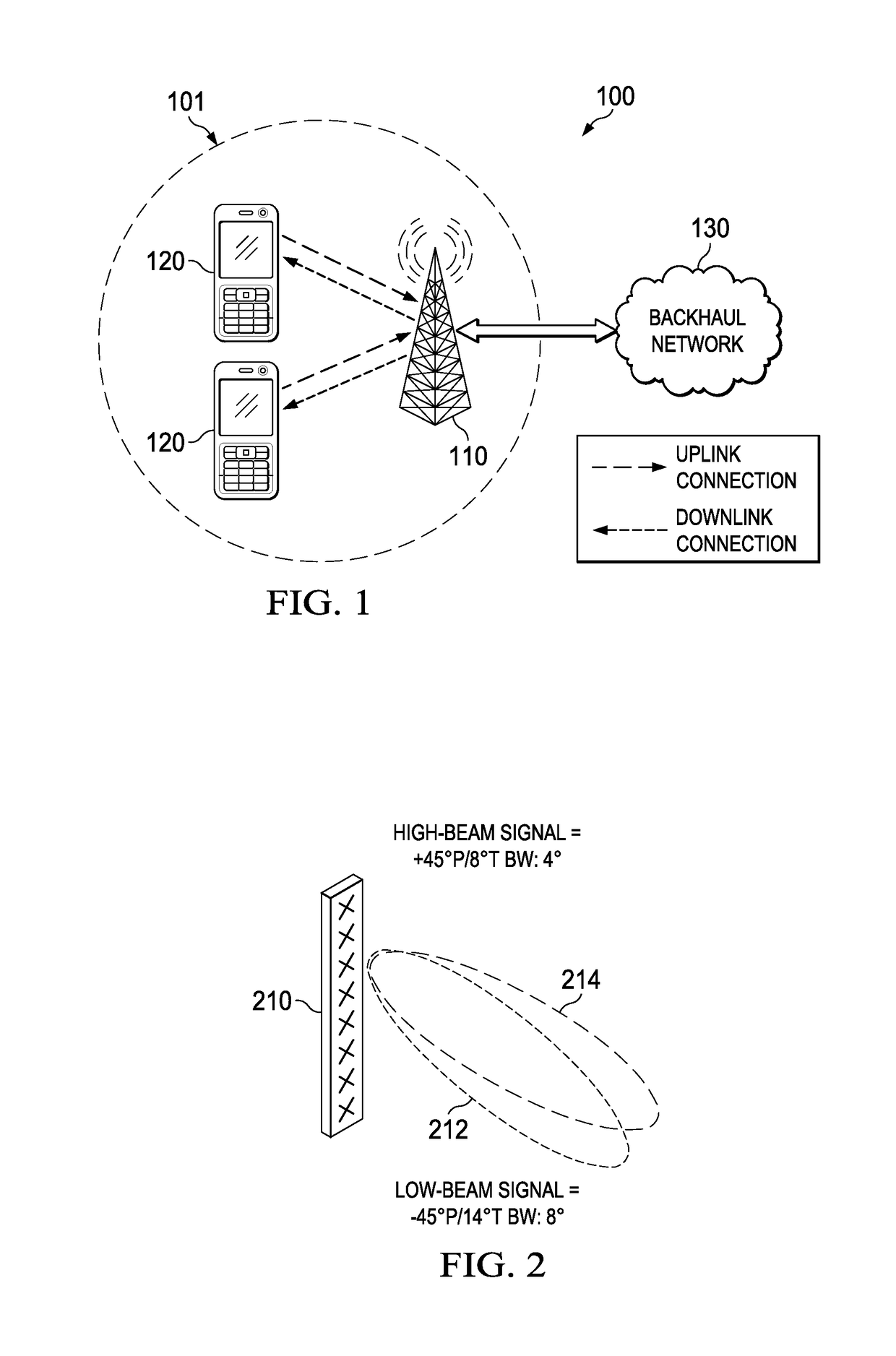
TECHNICAL FIELD[0001]The present invention relates to telecommunications, and, in particular embodiments, to an apparatus and method to configure antenna beam width.BACKGROUND[0002]In cross-polarized antennas systems for wireless or cellular communications, such as for Long Term Evolution (LTE), the antenna is designed to emit two cross-polarized radio frequency (RF) beams at +45° and −45° polarization respectively. Further, the two polarizations are set to the same down tilt angle, for example 8° for each of the two polarized beams. To ensure proper multiple-input and multiple-output (MIMO) operation, multiple cross-polarized antennas need to have the same coverage, which is significantly impacted by their down tilt angles. However, the current setup of the cross-polarized antennas, with a fixed down tilt angle of the two polarized beams, does not offer any MIMO or beamforming functionality in the elevation dimension. There is a need for an improved cross-polarized antennas design ...

Claims


Application Information

Patent Timeline
Patent Type & Authority Patents(United States)
IPC IPC(8): H04B7/0456H01Q21/24H01Q1/24H04B7/0452H04B7/10H01Q25/00H01Q3/26H01Q3/04H04W88/08
CPCH04B7/0456H01Q1/246H01Q3/26H01Q21/24H04B7/0452H04B7/0469H04B7/10H01Q25/001H04W88/08H01Q3/04H04B7/0617
Inventor PIAZZI, LEONARDZHAO, RENJIANMA, ZHENGXIANGFEUCHTINGER, STEFAN
Owner FUTUREWEI TECH INC
Learn More