Printing apparatus and platen

a printing apparatus and platen technology, applied in the direction of printing, other printing apparatus, etc., can solve the problems of reducing the capacity of the duct, affecting the efficiency of printing, so as to achieve the compatibility between waste ink recovery and secure marginless printing, suppress floating or flexing of the sheet, and secure the effect of marginless printing

Active Publication Date: 2019-01-22
CANON KK
View PDF47 Cites 1 Cited by
  • Summary
  • Abstract
  • Description
  • Claims
  • Application Information

AI Technical Summary

Benefits of technology

[0006]An object of the present invention is to provide a printing apparatus capable of securely performing marginless printing while suppressing floating or flexure of a sheet owing to the suction of the sheet, and furthermore, capable of securely achieving the compatibility between waste ink recovery and sheet suction without increasing the size of the apparatus, and a platen.
[0008]According to the present invention, it is possible to securely perform marginless printing while suppressing floating or flexure of a sheet owing to the suction of the sheet, and furthermore, to securely achieve the compatibility between waste ink recovery and sheet suction without increasing the size of the apparatus.

Problems solved by technology

Therefore, the capacity of the duct must be reduced, whereby negative pressure control by a negative pressure generating fan is liable to become unstable.
In addition, the arrangement of the waste ink tank also is limited.

Method used


Image

  • Printing apparatus and platen
  • Printing apparatus and platen
  • Printing apparatus and platen

Examples


Embodiment Construction

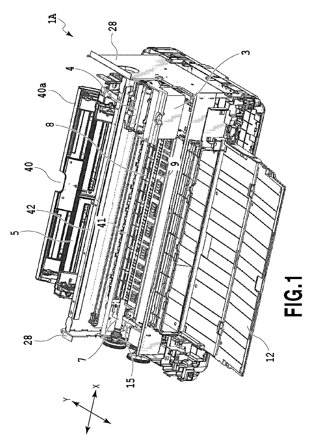
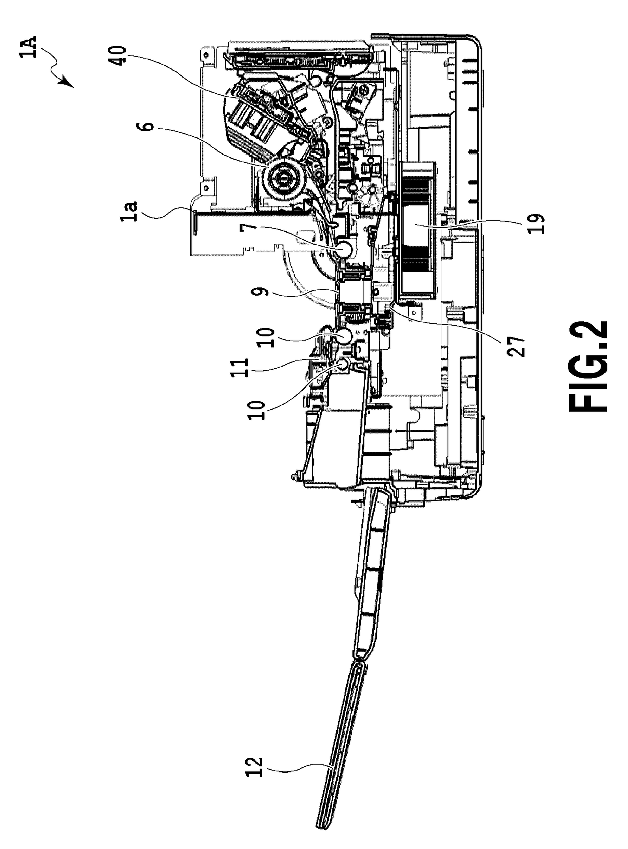
[0030]A description will be given below of an embodiment of a printing apparatus according to the present invention. Hereinafter, the present invention will be described by way of an inkjet printing apparatus of a serial type for performing printing by reciprocating a printhead in a direction transverse to a sheet conveyance direction, the printhead being capable of ejecting ink on a sheet that is intermittently conveyed in a predetermined direction. The present invention is applicable to not only a printing apparatus of a serial type but also a line printing apparatus for sequentially performing printing by the use of an elongated printhead. Moreover, the printing apparatus is applicable to not only a printing apparatus having a single function but also a multiple function printer equipped with a copying function, a facsimile function, and the like.

1. Outline of Apparatus

[0031]A description will be given of a printing apparatus 1 in the present embodiment. FIG. 1 is a perspective v...


PUM


Abstract

A printing apparatus includes a suction unit configured to allow a negative pressure, by which a sheet is sucked to a supporting portion, to act on the sheet; and ink receivers configured to receive ink ejected outside of the sheet. Waste ink ejected to the ink receivers is guided to a waste ink discharge port formed on an outer peripheral wall of a platen through waste ink channels. A sheet sucking mechanism configured to apply the negative pressure is disposed adjacent to the suction unit. A discharging mechanism configured to forcibly discharge waste ink outside of the platen is connected to the waste ink discharge port.

Description

BACKGROUND OF THE INVENTION[0001]Field of the Invention[0002]The present invention relates to an inkjet printing apparatus provided with a platen for supporting a sheet.[0003]Description of the Related Art[0004]An inkjet printing apparatus disclosed in Japanese Patent Laid-Open No. 2006-187903 uses a suction platen that sucks a sheet by a negative pressure. Furthermore, a duct and a waste ink tank are disposed under the platen so as to recover ink (waste ink) discarded during marginless printing.[0005]The inkjet printing apparatus disclosed in Japanese Patent Laid-Open No. 2006-187903 is configured such that a guide channel extending from the platen to the waste ink tank is formed sideways of the duct, that is, is flush with the duct. Therefore, the capacity of the duct must be reduced, whereby negative pressure control by a negative pressure generating fan is liable to become unstable. In addition, the arrangement of the waste ink tank also is limited. Consequently, the large size ...

Claims


Application Information

Patent Timeline
Patent Type & Authority Patents(United States)
IPC IPC(8): B41J11/00B41J29/17B41J11/06B41J2/165B41J2/17
CPCB41J11/0085B41J11/0065B41J11/06B41J29/17B41J2002/1742B41J2/16523B41J2/1721B41J2/01B41J2/185B41J11/0005B41J13/10B41J29/02
Inventor OGASAWARA, SEIJIKURATA, TETSUJITSUKUDA, MASAKAZUONUMA, TAKAHIDESAITO, YASUNORI
Owner CANON KK
Why Eureka
Try Eureka