
System and method of increasing reliability in high pressure switches

a high-pressure switch, reliability technology, applied in the closing of explosion switches, explosion-operated switches, wellbore/well accessories, etc., can solve the problems of reducing the reliability of the entire switch and therefore the entire gun, causing problems for high-pressure switches, and failure of switches

Inactive Publication Date: 2019-01-15
TRAFTON DANIEL S
View PDF6 Cites 4 Cited by
  • Summary
  • Abstract
  • Description
  • Claims
  • Application Information

AI Technical Summary

Benefits of technology

The present invention is a system and method for improving the reliability of high pressure switches used in perforating guns for oil and gas wells. The technical effects of this patent include increasing the reliability of high pressure switches, reducing failures caused by high forces, and ensuring the switch can still be controlled even if there are many switches in a gun. The invention addresses issues with conventional high pressure switches by incorporating a system of press fit parts to keep the assembly of conducting and non-conducting parts together, but this reduces the reliability of the entire switch and increases the risk of failure of the entire gun if a switch fails. The invention proposes a new system that addresses these issues by incorporating a piston insulator and a sliding electrical connection to improve the reliability of the switch.

Problems solved by technology

Press fit connections between the elements of a conventional high pressure switch reduce reliability of the entire switch and therefore the entire gun.
Press fit parts are cheap to produce but create issues for high pressure switches.
First, the high forces imparted on the switch overcome the press fit and cause failures in the switch.
For example, the press fitted firing pin insulator can be inadvertently ejected from the switch when the press fit between the case of the switch and the firing pin insulator is overcome by the force of the firing pin and the piston.
Second, the press fit between the piston assembly and the case can be too great for the explosive force to move the piston.
Third, the electrical connection between the firing pin and the rest of the circuit is physically unable to resist the stress of the firing pin in motion because the wiring is soldered adjacent the exposed tip of the firing pin, soldered with a spring surrounding the wire and the tip of the firing pin.
The force of the firing pin starting and stopping causes mechanical failure of the solder joint.

Method used


Image

  • System and method of increasing reliability in high pressure switches
  • System and method of increasing reliability in high pressure switches
  • System and method of increasing reliability in high pressure switches

Examples


Embodiment Construction

[0050]Illustrative embodiments of the apparatus for a system and method of increasing reliability in a high pressure switch are provided below. It will of course be appreciated that in the development of any actual embodiment, numerous implementation-specific decisions will be made to achieve the developer's specific goals, such as compliance with assembly-related and business-related constraints, which will vary from one implementation to another. Moreover, it will be appreciated that such a development effort might be complex and time-consuming, but would nevertheless be a routine undertaking for those of ordinary skill in the art having the benefit of this disclosure.

[0051]A system is herein described that overcomes the limitations of the current high pressure switches for electrically coupling explosive charges. The elements described herein increase the reliability of the system and reduce failures.

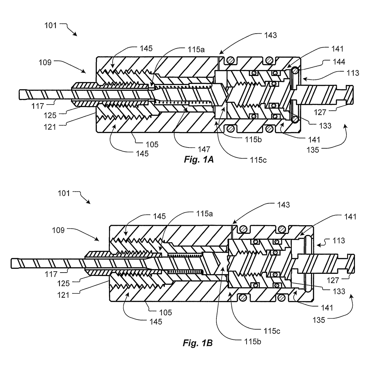
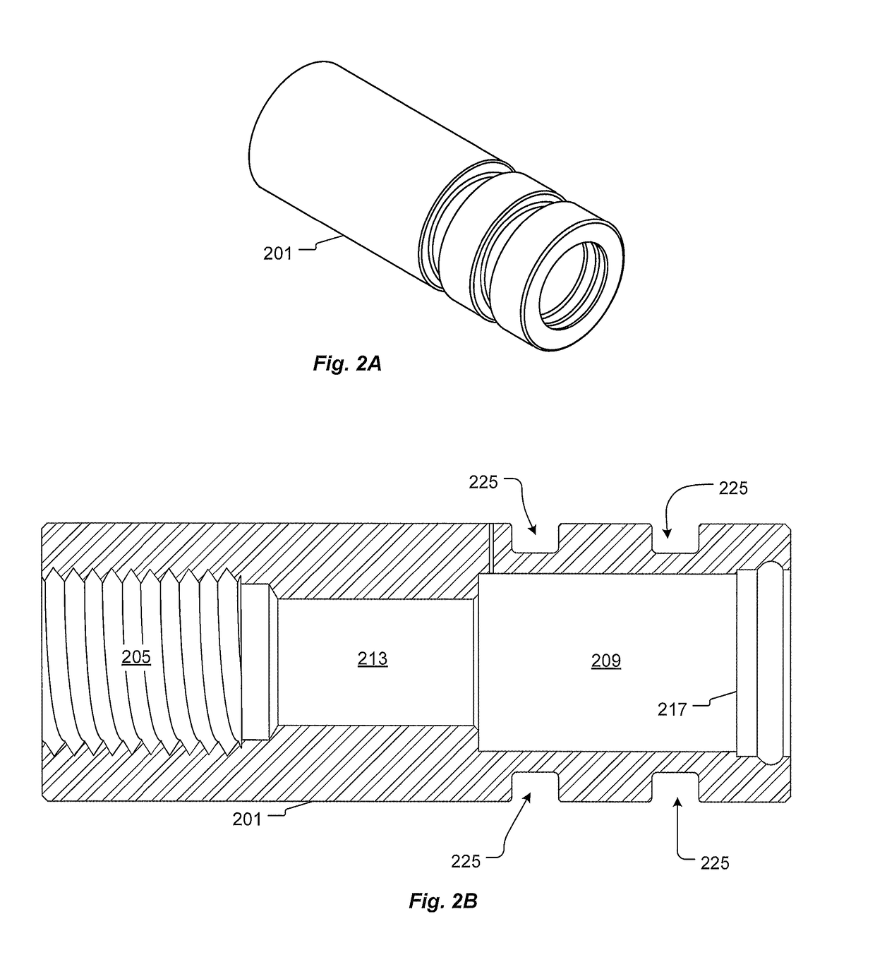
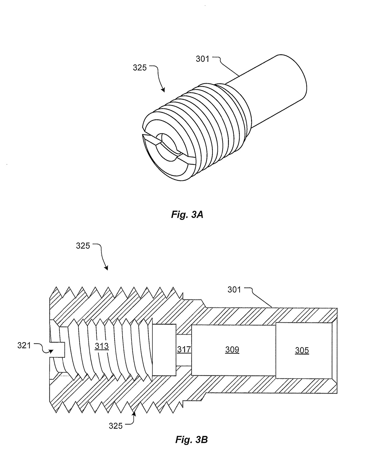
[0052]Referring now to FIG. 1A in the drawings, a cross section view of a high p...


PUM


Abstract

A high pressure switch for controlling electrical signals between elements of a gun for perforating hydrocarbon wells. The switch uses mechanical energy from an explosion to change from one electrical path to a second electrical path. The switch has a piston that translates from the shockwave to electrical connect a firing pin to a conductive member while opening an electrical path from the piston to the firing pin.

Description

CROSS REFERENCE TO RELATED APPLICATIONS[0001]This application is a continuation-in-part of U.S. patent application Ser. No. 15 / 055,513 filed 26 Feb. 2016, titled “System and Method of Increasing Reliability in High Pressure Switches;” which is hereby incorporated by reference for all purposes as if fully set forth herein.BACKGROUND1. Field of the Invention[0002]The present invention relates generally to electrical switches for oil well equipment, and more specifically to a system and method for improving reliability of high pressure switches located in perforating guns used for the perforation of oil and gas wells.2. Description of Related Art[0003]Oil and gas wells are perforated to allow hydrocarbons to flow from outside the well to inside the well. Perforations in the well casing are produced by explosive charges arranged in a “gun.” Guns comprises several explosive charges wired to several switches. Controlling the explosive charges is a critical task. Insuring the user can cont...

Claims


Application Information

Patent Timeline
Patent Type & Authority Patents(United States)
IPC IPC(8): E21B43/1185H01H39/00
CPCE21B43/1185H01H39/004F42D1/045H01H35/38
Inventor TRAFTON, DANIEL S.
Owner TRAFTON DANIEL S
Learn More