Method for vacuum-forming dental appliance

a vacuum-forming, dental appliance technology, applied in the field of oral appliances, can solve the problems of unsatisfactory patient treatment, unaccepted patient compliance, and unfavorable patients, and achieve the effect of preventing or at least alleviating snoring

Active Publication Date: 2019-01-15
FRANTZ DESIGN
View PDF11 Cites 0 Cited by
  • Summary
  • Abstract
  • Description
  • Claims
  • Application Information

AI Technical Summary

Benefits of technology

[0010]It is well documented in the literature that an oral appliance that opens the bite and moves the mandible forward will greatly reduce sleep apnea and snoring. It is also documented that these appliances are capable of producing considerable discomfort to patients, unwanted movement of their teeth, and / or tempromandibular joint pain as well as other problems.
[0013]What is needed is an adjustable oral snoring / sleep apnea appliance which is effective, which has high patient acceptance, and which will not cause temporomandibular joint problems, unwanted tooth movement or soreness.
[0014]The appliance of the present disclosure greatly reduces, or eliminates, sleep apnea and snoring, while alleviating temporomandibular joint problems, unwanted tooth movement and soreness, with complete adjustability of the appliance both in the amount of forward movement of the lower jaw, and in the amount of vertical bite opening. Another object is a mandibular advancement appliance with high patient acceptance, comfort, and treatment success. Another object is to make the appliance in a single office visit using machines normally supplied in a typical dentist's office.

Problems solved by technology

It is also documented that these appliances are capable of producing considerable discomfort to patients, unwanted movement of their teeth, and / or tempromandibular joint pain as well as other problems.
Bulky “boil & bite” appliances have not been effective and have not had patient acceptance or compliance.
These uncomfortable devices have driven patients away from wanting to be treated by a custom oral appliance.
In summary, appliances exist in which the amount of advancement may be changed, but the changes result in a new fixed position of the mandible creating pain and discomfort.

Method used


Image

  • Method for vacuum-forming dental appliance
  • Method for vacuum-forming dental appliance
  • Method for vacuum-forming dental appliance

Examples


Embodiment Construction

[0022]Embodiments herein relate to methods for manufacturing an oral appliance that requires only a single office visit.

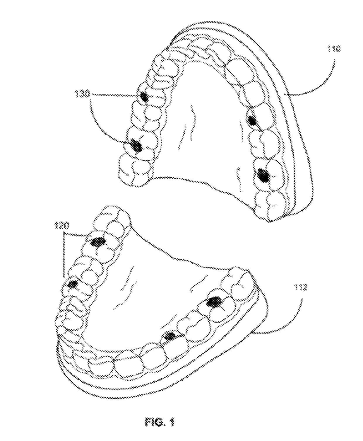
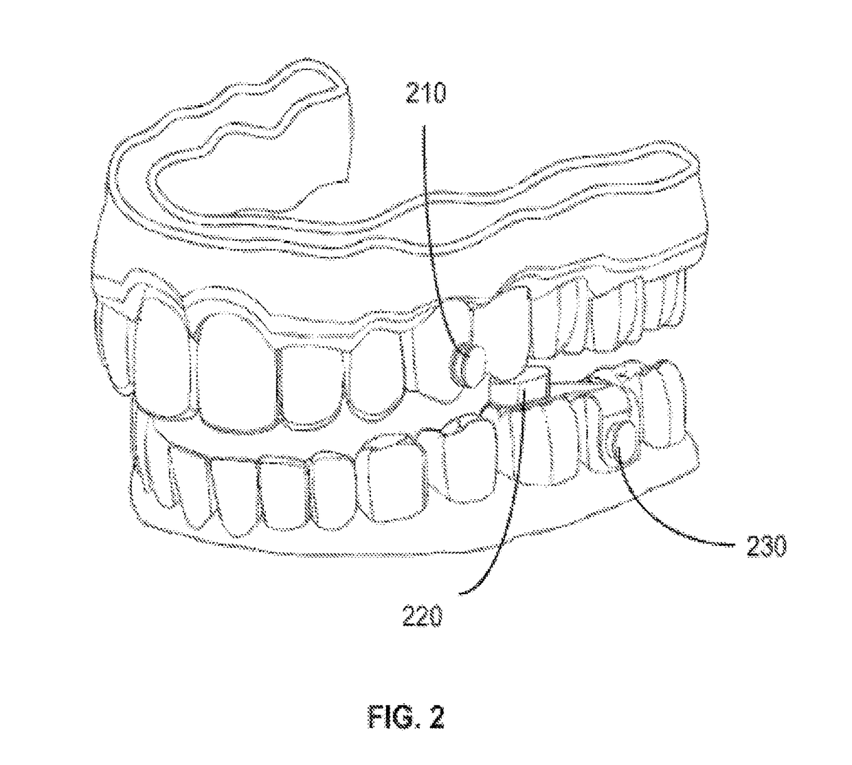
[0023]During the office visit, a patient can be fitted for an oral appliance by first obtaining an upper (maxillary) and lower (mandibular) impression of the teeth and supporting soft tissue including the upper hard palate. This impression must be extremely accurate to avoid tooth soreness, and / or movement when the appliance is placed in the patient's mouth. The impression is taken by: (1) having the patient rinse with a pre-impression mouth wash to eliminate any saliva distortion; and (2) pouring the impressions immediately to avoid distortion using a hard lab stone.

[0024]In an alternate embodiment, instead of taking impressions, a patient can be visually examined with high definition optics capable of generating 3D images and Computer Aided Design (CAD) images. For example, 3D x-rays can be converted to CAD images that accurately portray the same information that...


PUM

PropertyMeasurementUnit
distanceaaaaaaaaaa
distanceaaaaaaaaaa
distanceaaaaaaaaaa

Abstract

An appliance and methods are described that include embodiments of a mandibular advancement or positioning device which can use elastic bands to pull the jaw forward. The appliance has an upper plastic tray conforming to the patient's upper teeth and including 3D printed sets of retention hooks coupled to the upper plastic tray via being encased in plastic, one on the right and one on the left anterior buccal portion of an upper plastic base. The appliance also has a lower plastic tray conforming to the patient's lower teeth including mandibular dentition, and includes having a 3D printed bite pad which opens the bite vertically. The lower tray also has a set of 3D printed plastic retention hooks encased in plastic extending outwardly from the teeth, one on the right and one on the left of the posterior buccal portion of the lower plastic base. Elastic bands of different lengths and strengths are attached to both the top and bottom retention hooks on both sides of the trays to pull the mandible forward for treatment.

Description

CROSS-REFERENCE TO RELATED APPLICATIONS[0001]An Application Data Sheet (ADS) has been filed on the filing date of this application, it is incorporated by reference herein. Any applications claimed on the ADS for priority under 35 U.S.C. §§ 119, 120, 121, or 365(c), and any and all parent, grandparent, great-grandparent, etc. applications of such applications, are also incorporated by reference, including any priority claims made in those applications and any material incorporated by reference, to the extent such subject matter is not inconsistent herewith.[0002]The present application is related to and / or claims the benefit of the earliest available effective filing date(s) from the following listed application(s) (the “Priority Applications”), if any, listed below (e.g., claims earliest available priority dates for other than provisional patent applications or claims benefits under 35 USC § 119(e) for provisional patent applications, for any and all parent, grandparent, great-grand...

Claims


Application Information

Patent Timeline
Patent Type & Authority Patents(United States)
IPC IPC(8): B29C51/12B29C69/00B29C64/118B29C64/112B29C64/106B29C67/00B29C70/70A61F5/56B29C51/10B29C51/46B33Y50/02B33Y30/00B33Y10/00B29K105/00B29L31/00
CPCB29C51/10B29C51/46B29C64/106B29C64/112A61F5/566B29C69/001B29C64/118B33Y50/02B29K2105/256B29L2031/753B33Y10/00B33Y30/00B29C64/00B29C64/386
Inventor FRANTZ, JOSEPH LEEFRANTZ, DONALD
Owner FRANTZ DESIGN
Why Eureka
Try Eureka