
Method of using power grid as large antenna for geophysical imaging

a geophysical imaging and power grid technology, applied in transmission, data processing applications, instruments, etc., can solve the problems of long power transmission lines, many kilometers in length, and damage to electrical transmission equipment, especially transformers, and the damage of gic effects

Active Publication Date: 2019-01-08
NASA
View PDF2 Cites 0 Cited by
  • Summary
  • Abstract
  • Description
  • Claims
  • Application Information

AI Technical Summary

Benefits of technology

The patent describes a way to create a low-cost and autonomous magnetometer to measure the effects of geomagnetic storms on scientific instruments and high-voltage power transmission systems. By measuring the changes in GIC (ground impact current) caused by the storms, the system can provide valuable information about the near space environment. By using a large high-voltage power transmission system as an antenna, the system can extract unprecedented spatiotemporal space, physical, and geological information from distributed GIC observations. Overall, this invention allows for improved monitoring and protection against geomagnetic events that can affect power transmission systems.

Problems solved by technology

GIC can be harmful to the power grid and thus the information is valuable also for the transmission system operators.
Long power transmission lines, for example, of many kilometers in length, are subject to damage by the GIC effect, especially in more modern high-voltage, low-resistance lines.
The nearly direct currents induced in high-voltage power transmission lines from geomagnetic storms are harmful to electrical transmission equipment, especially transformers.
Such induced currents can induce core saturation, constrain transformer performance, trip various safety devices, and cause coils and cores to heat up.
In some cases heat generated can disable or destroy a transformer, or even induce a chain reaction that can overload transformers throughout a system.
A faulty transformer can also affect a linked generator by acting as an unbalanced load to a generator, causing negative sequence current in the stator and consequently heating of the rotor.

Method used


Image

  • Method of using power grid as large antenna for geophysical imaging
  • Method of using power grid as large antenna for geophysical imaging
  • Method of using power grid as large antenna for geophysical imaging

Examples


Embodiment Construction

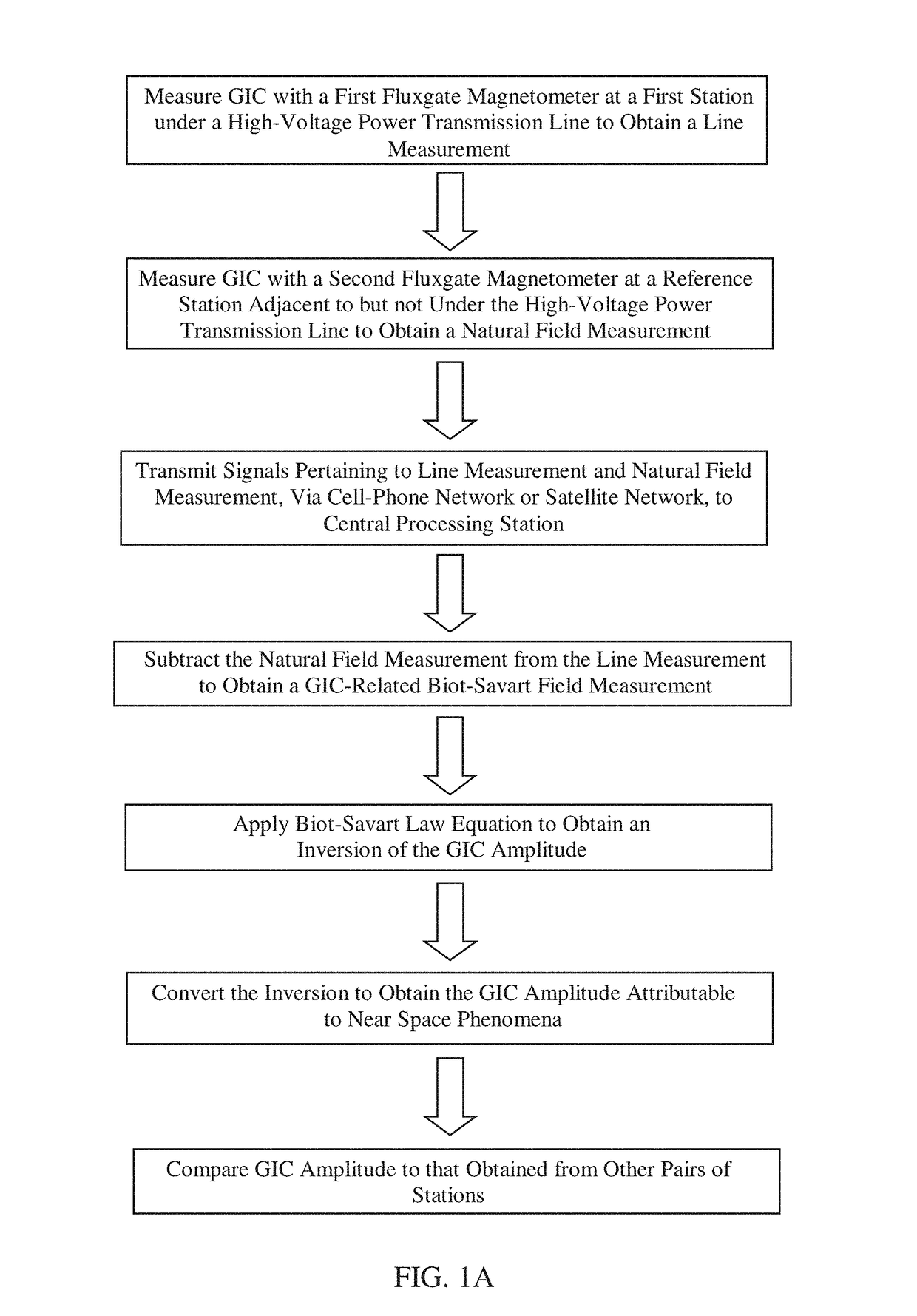
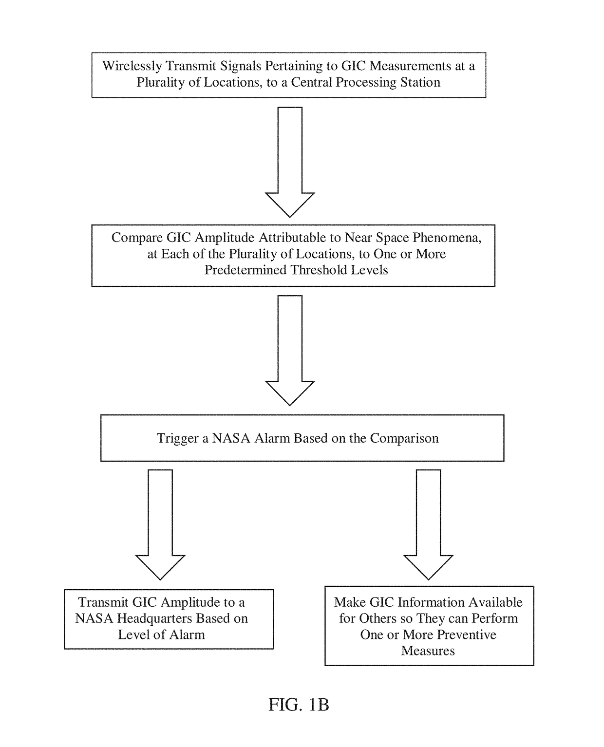
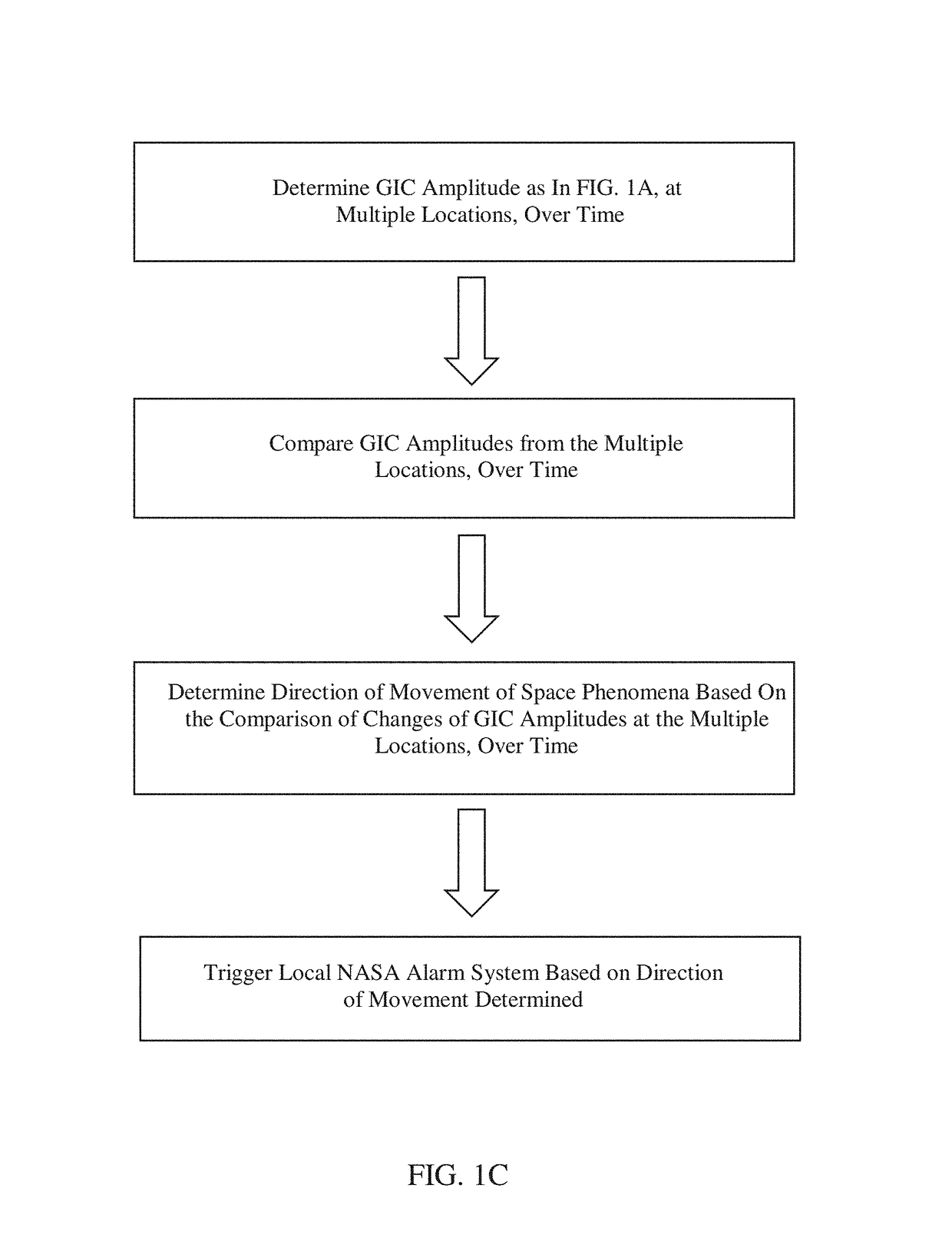
[0015]According to various embodiments of the present invention, a method of determining the amplitude of a geomagnetically induced current (GIC) in a high-voltage power transmission line, due to near space phenomena, is provided. The method can comprise measuring GIC with a first fluxgate magnetometer at a first magnetometer station under a high-voltage power transmission line, to obtain a GIC line measurement. The first magnetometer station can be located on a platform immediately below the high-voltage power transmission line, or located on the ground directly underneath the high-voltage power transmission line. The first magnetometer station can be positioned, for example, five feet below, 10 feet below, 20 feet below, 50 feet below, or 100 feet below the high-voltage power transmission line. The first magnetometer station can be attached to a support pole or structure supporting the high-voltage power transmission line. A second fluxgate magnetometer can be used to measure GIC ...


PUM


Abstract

A high-voltage power transmission system is used as an extremely large antenna to extract spatiotemporal space, physical, and geological information from geomagnetically induced currents (GIC). A differential magnetometer method is used to measure GIC and involves acquiring line measurements from a first fluxgate magnetometer under a high-voltage transmission line, acquiring natural field measurements from a reference magnetometer nearby but not under the transmission line, subtracting the natural field measurements from the line measurements, and determining the GIC-related Biot-Savart field from the difference. NASA warning and alarm systems can be triggered based on determinations of GIC amplitude levels that exceed a set threshold value.

Description

STATEMENT REGARDING FEDERALLY SPONSORED RESEARCH OR DEVELOPMENT[0001]The invention described herein was made in part by employees of the United States Government and may be manufactured and used by or for the Government of the United States of America for governmental purposes without the payment of any royalties thereon or therefore.FIELD OF THE INVENTION[0002]The present invention relates to a high-voltage power transmission system and methods of detecting near space geomagnetic phenomena.BACKGROUND OF THE INVENTION[0003]Geomagnetically induced currents (GIC) carry information about near space phenomena, which is of NASA science interest. GIC can be harmful to the power grid and thus the information is valuable also for the transmission system operators.[0004]When magnetic fields move about in the vicinity of a conductor such as a high-voltage power transmission line, a GIC is produced in the conductor. This happens on a large scale during geomagnetic storms on practically all lon...

Claims


Application Information

Patent Timeline
Patent Type & Authority Patents(United States)
IPC IPC(8): G01R19/165G01R31/02H04B7/0408
CPCG01R31/021G01R19/165G01R29/0814G06Q50/06G06Q10/06G01R31/58
Inventor PULKKINEN, ANTTI A.BONALSKY, TODD M.AMES, TROYHOSTETTER, CARL F.
Owner NASA
Learn More