
System and method for identifying devices in a room on a network

a network and device technology, applied in the field of system and method for identifying devices in a room on a network, can solve the problems of disadvantageous access to sources, lack of a single user, and difficulty in communicating in a room of a hospital network, so as to facilitate in-room control, improve connectivity, and improve patient experience.

Active Publication Date: 2019-01-01
GYRUS ACMI INC (D B A OLYMPUS SURGICAL TECH AMERICA)
View PDF10 Cites 5 Cited by
  • Summary
  • Abstract
  • Description
  • Claims
  • Application Information

AI Technical Summary

Benefits of technology

The patent describes a system and method that allows a remote viewer to create a virtual presence in a hospital room or other medical environment. This is done through multiple displays in the room that correspond to different sources, such as cameras or video screens. The virtual presence system is controlled by a processing arrangement on a controller that selects the display that the remote viewer will see. This ensures that the local user has exclusive control of the sources in the room, while the remote viewer only has a virtual presence. The system can also include a graphical user interface that guides the local staff through a medical procedure and helps improve the patient experience. Additionally, the system includes a controller or control computer that is operatively connected to a video matrix switch, making it easier to control and manipulate the sources in the room. Overall, the patent describes a technology that enhances communication and collaboration in medical environments.

Problems solved by technology

Communication in a room of a hospital network, or other appropriate network, is often hindered by the multitude of formats used for each source available in the room.
It is a challenge to effectively communicate between the various sources using current communication and network techniques.
There is a lack of a system that allows a single user to manipulate all sources within a room using a standardized technique.
These systems disadvantageously provide access to the sources themselves directly to the remote viewer.
Accordingly, a local in-room user experiences undesirable interruptions and potential loss of control of the procedure and the devices and sources that perform the functions of the procedure.

Method used


Image

  • System and method for identifying devices in a room on a network
  • System and method for identifying devices in a room on a network
  • System and method for identifying devices in a room on a network

Examples


Embodiment Construction

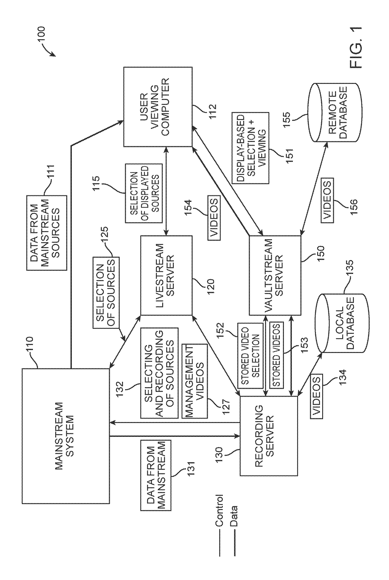
[0037]A system and method for controlling and selecting sources and other content in a room on a network allows a local user to control a plurality of sources in a room. The system further enables a remote viewer to experience a virtual presence in the room using a control computer by selecting from available displays corresponding to sources in the room. The room is a room in a medical environment, such as, but not limited to, an operating room (OR) in a hospital. The term “medical environment” as used herein, refers to a location in which a surgical, diagnostic, therapeutic, or other medical procedure is performed. The medical environment, or “medical treatment location” (used interchangeably herein) typically, but not always, has a doctor, hospital staff, and other medical personnel present, that assist in a medical procedure. The medical environment includes, but is not limited to, a hospital, trauma center, doctor's office, surgical center, and other locations known to those ha...


PUM


Abstract

A system and method for controlling and selecting sources in a room on a network. The system allows a remote viewer to create a virtual presence within the room by providing the available displays, corresponding to the sources, to the remote viewer. The system includes a standardizing technique for improving the communication and overall switching of data for streaming on a network. The system can include a recording server for performing dual recording of the video files in each of a local database and a remote database. A graphical user interface (GUI) display is provided to guide a local user through a medical procedure in the standardized system.

Description

RELATED APPLICATIONS[0001]This application claims the benefit under 35 U.S.C. § 120 as a continuation of U.S. application Ser. No. 13 / 708,903 filed Dec. 7, 2012, entitled “SYSTEM AND METHOD FOR CONTROLLING AND SELECTING SOURCES IN A ROOM ON A NETWORK”, which claims the benefit under 35 U.S.C. § 119(e) to U.S. Provisional Application Ser. No. 61 / 568,013, filed Dec. 7, 2011, entitled “SYSTEM AND METHOD FOR CONTROLLING AND SELECTING SOURCES IN A ROOM ON A NETWORK”, all of which are hereby incorporated herein by reference in their entireties for all purposes.FIELD OF THE INVENTION[0002]The present invention relates to systems and methods for controlling a plurality of video and other information sources in a room connected through a network.BACKGROUND OF THE INVENTION[0003]In a hospital environment, it is crucial for all rooms, and more particularly, the various sources and personnel within each room to communicate effectively. The sources within the room can include a control computer,...

Claims


Application Information

Patent Timeline
Patent Type & Authority Patents(United States)
IPC IPC(8): H04L29/06A61B34/20A61B90/20A61B1/00A61B1/313H04N5/232A61B5/00A61B90/00A61B8/00A61B6/00A61B34/00H04N7/01H04N9/79H04N5/222H04N5/225
CPCH04L65/60H04N7/0125H04N9/79H04N5/2228H04N5/23216A61B1/00011A61B1/3132A61B5/0002A61B6/56A61B8/56A61B34/20A61B90/20A61B90/361A61B90/37A61B34/25H04N2005/2255H04N7/147H04N7/155G16H80/00G16H40/67H04N7/181G06Q10/109G16H30/20H04N23/62H04N23/555G16H40/63G06F3/0482G09B23/285H04L67/12
Inventor MITCHELL, EDDIE E.RENZI, PETER
Owner GYRUS ACMI INC (D B A OLYMPUS SURGICAL TECH AMERICA)
Learn More