
Dialysis machine, and method of determining the calcification in a dialysis machine

a dialysis machine and calcification technology, applied in the field of dialysis, can solve the problems of failure to achieve the treatment goal, failure to produce dialysis liquid, calcium deposited in the dialysis machine,

Active Publication Date: 2018-12-18
FRESENIUS MEDICAL CARE DEUTSCHLAND GMBH
View PDF12 Cites 8 Cited by
  • Summary
  • Abstract
  • Description
  • Claims
  • Application Information

AI Technical Summary

Benefits of technology

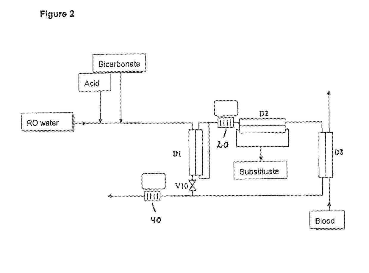
The present invention aims to improve dialysis machines by recognizing calcification before it causes treatment abortion and ensures safe treatment with low calcium ion concentrations over a long period. Sensors are placed upstream and downstream of filters to detect calcification on both sides. A bypass line is also included to connect sensors without filtering to compare measurement values or calibrate sensors.

Problems solved by technology

Under extreme conditions such as, for example, with an additionally low acid content, with long dialysis times or for the case that no decalcifying disinfection is carried out between two dialysis treatments, the said lime deposits can result in failure of the production of dialysis liquid, for example, by blocking of the conveying pumps or by calcification of dialysis liquid filters.
Whereas the problem of calcification at the machine side, which can result in an abortion of the dialysis and thus in a non-achievement of the treatment goal, is thus generally known, the effects of the lime deposition in the machine on the calcium supply to the patient have previously only been rarely looked at.
It is evident that the calcium deposited in the dialysis machine, which is precipitated in the form of lime, can no longer reach the patient.
The case can thus occur that the patient is treated with a dialysis liquid for a fairly long time whose Ca2+-ion concentration is below the concentration of the ionized calcium in the plasma, which can have the consequence that calcium is removed from the patient in an unwanted manner in the dialysis treatment.
It can therefore be imagined that negative effects on the patient can occur as a consequence of the machine calcification.

Method used


Image

  • Dialysis machine, and method of determining the calcification in a dialysis machine
  • Dialysis machine, and method of determining the calcification in a dialysis machine
  • Dialysis machine, and method of determining the calcification in a dialysis machine

Examples


Embodiment Construction

[0038]Further scope of applicability of the present, invention will become apparent from the detailed description given hereinafter. However, it should be understood that the detailed description and specific examples, while indicating preferred embodiments of the invention, are given by way of illustration only, since various changes and modifications within the spirit and scope of the invention will become apparent to those skilled in the art from this detailed description.

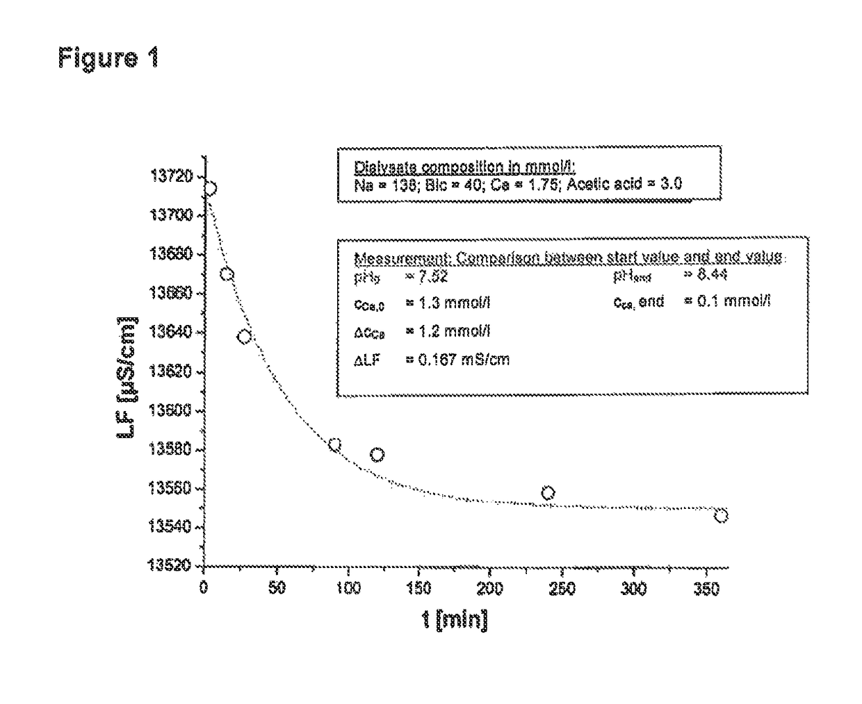
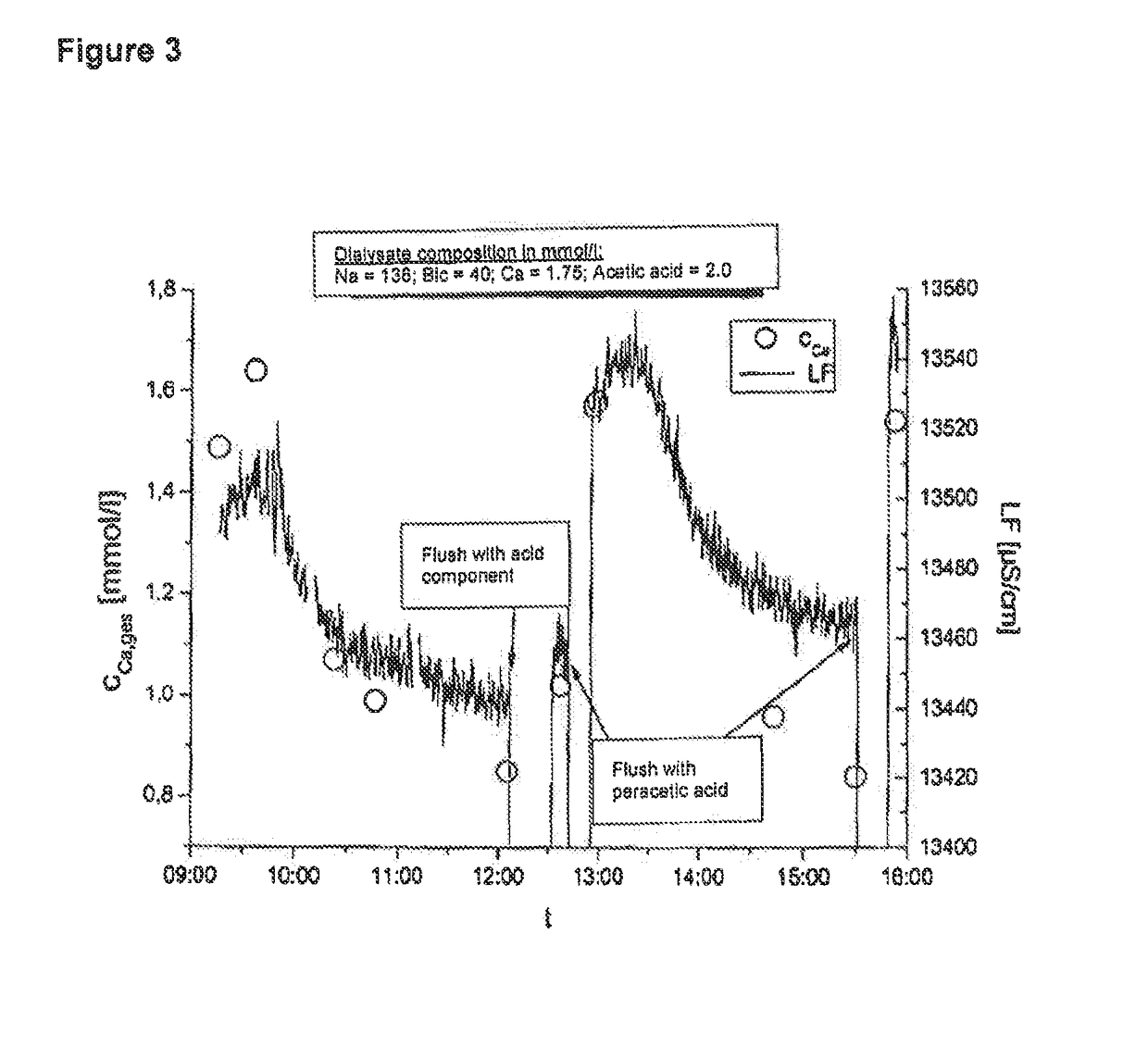
[0039]The conductivity of the dialysis liquid is determined by its individual components. The main contribution of the conductivity is due to NaCl, but the Ca2+ ions present in relatively low concentrations also contribute to the conductivity. If a dialysis liquid containing both Ca2+ and HCO3− is in contact with the atmosphere, the outgasing of CO2 results in a consumption of hydrogen carbonate and thus in a pH value shift into the alkaline, which in turn effects a precipitation of calcium carbonate. This is il...


PUM


Abstract

A dialysis machine has at least one filter for the filtration of dialysis liquid and a device for determining calcification of the dialysis machine. The device has one or more sensors configured and arranged to detect either downstream, or upstream and downstream, of the at least one filter an ion concentration or a parameter representative of the ion concentration or of its change of the dialysis liquid, of a solution serving the decalcification or of another measuring solution. The device for determining the calcification of the dialysis machine has an evaluation or calcification unit configured to determine the calcification of the dialysis machine based on the ion concentration or parameter value detected by the sensor or sensors.

Description

CROSS-REFERENCE TO RELATED APPLICATION[0001]This application is a continuation application of U.S. patent application Ser. No. 12 / 448,979, filed Jul. 17, 2009, the disclosure of which is incorporated by reference as if fully set forth herein. The aforementioned U.S. patent application Ser. No 12 / 448,979 is a nationalization of PCT / EP08 / 000339 filed Jan. 17, 2008 and published in German, which claims priority to DE 10 2007 004 115.4, filed Jan. 26, 2007.BACKGROUND OF THE INVENTION[0002]1. Field of Invention[0003]The present invention relates to a dialysis machine comprising at least one filter for the filtration of the dialysis liquid and comprising means for determining the calcification of the dialysis machine. The invention further relates to a method of determining the calcification of a dialysis machine.[0004]2. Description of the Prior Art[0005]In the use of dialysis liquids which simultaneously contain high concentrations of calcium ions (Ca2+) and bicarbonate ions (HCO3−), th...

Claims


Application Information

Patent Timeline
IPC IPC(8): A61M1/16
CPCA61M1/1605A61M1/16A61M1/165A61M1/1607A61M1/1609A61M1/169A61M2205/7554A61M2205/3317A61M2205/3324A61M2205/3327A61M2205/702A61M2205/707
Inventor MAIERHOFER, ANDREASGAGEL, ALFREDGROSS, MALTEKOCH, MICHAEL
Owner FRESENIUS MEDICAL CARE DEUTSCHLAND GMBH
Learn More