
Operation display system, operation display device, and operation display program

a display system and display device technology, applied in the direction of instruments, computing, electric digital data processing, etc., can solve the problems of user inconvenience, inability to display necessary information at once, limited screen size of a single touch panel, etc., to prevent the deterioration of the operability of touch panels

Active Publication Date: 2018-12-11
KONICA MINOLTA INC
View PDF22 Cites 0 Cited by
  • Summary
  • Abstract
  • Description
  • Claims
  • Application Information

AI Technical Summary

Benefits of technology

The present invention aims to provide an operation display system, device, and program that can prevent difficulty in using touch panels caused by different standards of operation between devices.

Problems solved by technology

However, the size of the screen of a single touch panel is limited, and in some cases, necessary information cannot be displayed at once.
However, since the size of the screen the user can see at once is still limited, the portions that have been visible become now hidden, and this causes the user inconvenience.
On the other hand, the user might find it difficult to operate a touch panel having a high load criterion.
However, even if the operability of each touch panel is improved by using the technique disclosed in JP 2011-150737 A, the user still finds it difficult to operate touch panels having different levels of operability when multiple electronic devices are made to cooperate.
As a result, the touch panels do not function as intended by the user, and the user might find it burdensome.

Method used


Image

  • Operation display system, operation display device, and operation display program
  • Operation display system, operation display device, and operation display program
  • Operation display system, operation display device, and operation display program

Examples


embodiment

[0048](Embodiment)

[0049]

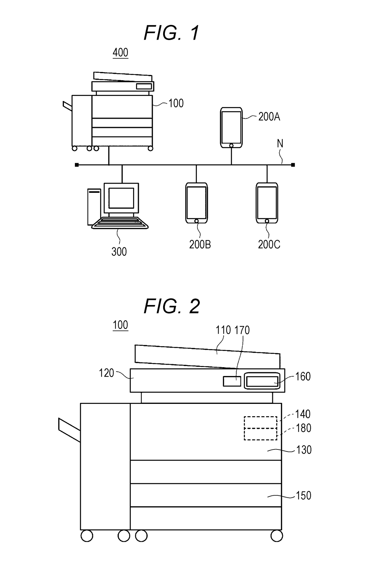
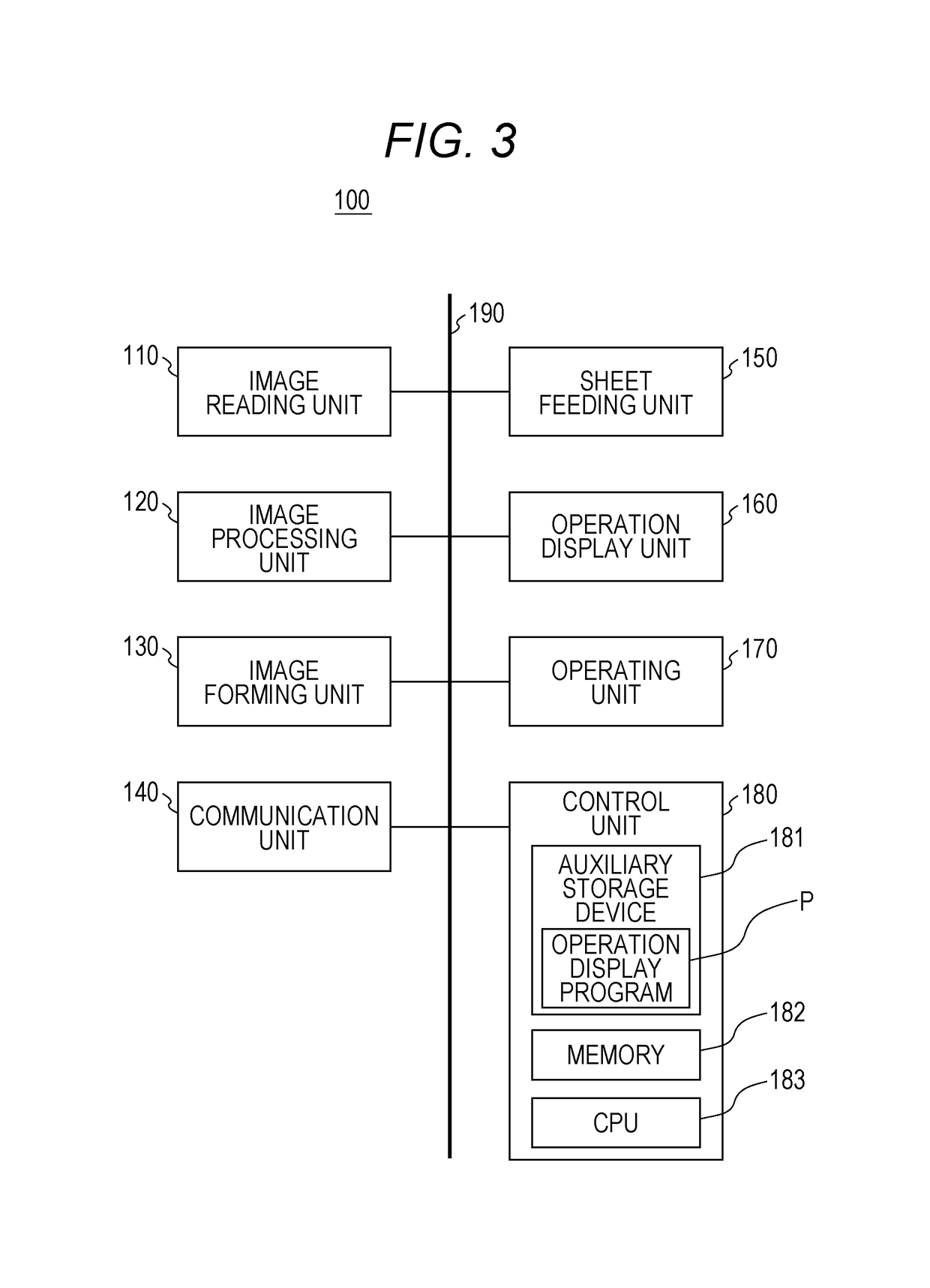
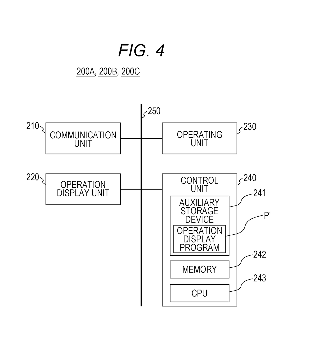
[0050]FIG. 1 is a schematic view for explaining the configuration of an operation display system according to an embodiment. FIGS. 2 and 3 are a side view and a block diagram, respectively, for roughly explaining the structure of the image forming apparatus shown in FIG. 1.

[0051]As shown in FIG. 1, an operation display system 400 includes an image forming apparatus 100, portable terminal devices 200A, 200B, and 200C, and a server 300. These components are connected to an access point, and are designed to be able to communicate with one another via a network N. Alternatively, any access point or network may not be used, and the components may be connected directly to one another. Also, the components may be connected wirelessly to one another, or may be connected to one another with wires.

[0052]The image forming apparatus 100 of this embodiment is an MFP, a printer, or a facsimile machine, for example. In the example case described below, the image forming app...


PUM


Abstract

An operation display system with a plurality of operation display devices each having a touch panel includes: a load criteria acquiring unit configured to acquire load criteria serving as criteria of pressing forces for the touch panels to accept an operation; an operation type acquiring unit configured to acquire types of operations to be performed on the touch panels with respect to objects displayed on screens of the operation display devices; and a control unit configured to control display on the screens of first and second operation display devices of the plurality of operation display devices in accordance with a result of comparison between the load criteria and the acquired types, the first and second operation display devices being in a cooperating state.

Description

[0001]The entire disclosure of Japanese Patent Application No. 2015-125156 filed on Jun. 22, 2015 including description, claims, drawings, and abstract are incorporated herein by reference in its entirety.BACKGROUND OF THE INVENTION[0002]Field of the Invention[0003]The present invention relates to an operation display system, an operation display device, and an operation display program.[0004]Description of the Related Art[0005]Electronic devices equipped with touch panels, such as portable telephone terminals including smartphones, and MFPs (MultiFunction Peripherals), are being widely used these days. A touch panel is normally formed by integrating a display device such as a liquid crystal display with an input device such as a touch pad. In a case where a user inputs information through a touch panel displaying image objects such an icon and a button on its screen, for example, the user can select the icon or the button to input information by touching the icon or the button with...

Claims


Application Information

Patent Timeline
Patent Type & Authority Patents(United States)
IPC IPC(8): G06F3/14G06F3/041H04N1/00G06F3/044G06F3/045G06F3/0484G06F3/0488G09G5/12
CPCG06F3/0416G06F3/045G06F3/0414G06F3/04845G06F3/04883G06F3/1423G06F3/1454G09G5/12H04N1/00129H04N1/00307H04N1/00411H04N1/00442H04N1/00474H04N1/00493H04N1/00503H04N1/00506G06F3/044H04N2201/0094G09G2300/026H04N2201/001H04N2201/0072H04N2201/0075G06F3/0484G06F3/0486G06F3/1431G06F3/1446G06F3/0488G06F2203/04106
Inventor SUGIMOTO, YASUAKI
Owner KONICA MINOLTA INC
Learn More