
Method for the detection of analytes via luminescence quenching

a luminescence quenching and analyte technology, applied in the field of analyte detection, can solve the problems of significant limitation on the usefulness of conjugated polymer sensors, and some inefficientness

Active Publication Date: 2018-12-11
THE UNIV OF QUEENSLAND
View PDF17 Cites 1 Cited by
  • Summary
  • Abstract
  • Description
  • Claims
  • Application Information

AI Technical Summary

Benefits of technology

This approach provides high sensitivity and selectivity in detecting explosives and explosives-related materials, minimizing false positives from everyday chemicals by utilizing a distinct luminescence response, enabling accurate identification.

Problems solved by technology

The ability to reliably detect a specific compound even at low concentrations is a continuing challenge, and there is the on-going need to provide new methodologies and devices to do this.
This approach to detection is indirect in nature and while being sensitive can be somewhat inefficient due to the time taken from sampling to detection.
The disadvantage of these latter methods is that they are reliant on a specific area of a substrate where the explosive analyte is present to be sampled, for example, swabbed.
This is a significant limitation on the usefulness of these existing conjugated polymer sensors.

Method used


Image

  • Method for the detection of analytes via luminescence quenching
  • Method for the detection of analytes via luminescence quenching
  • Method for the detection of analytes via luminescence quenching

Examples


example 1

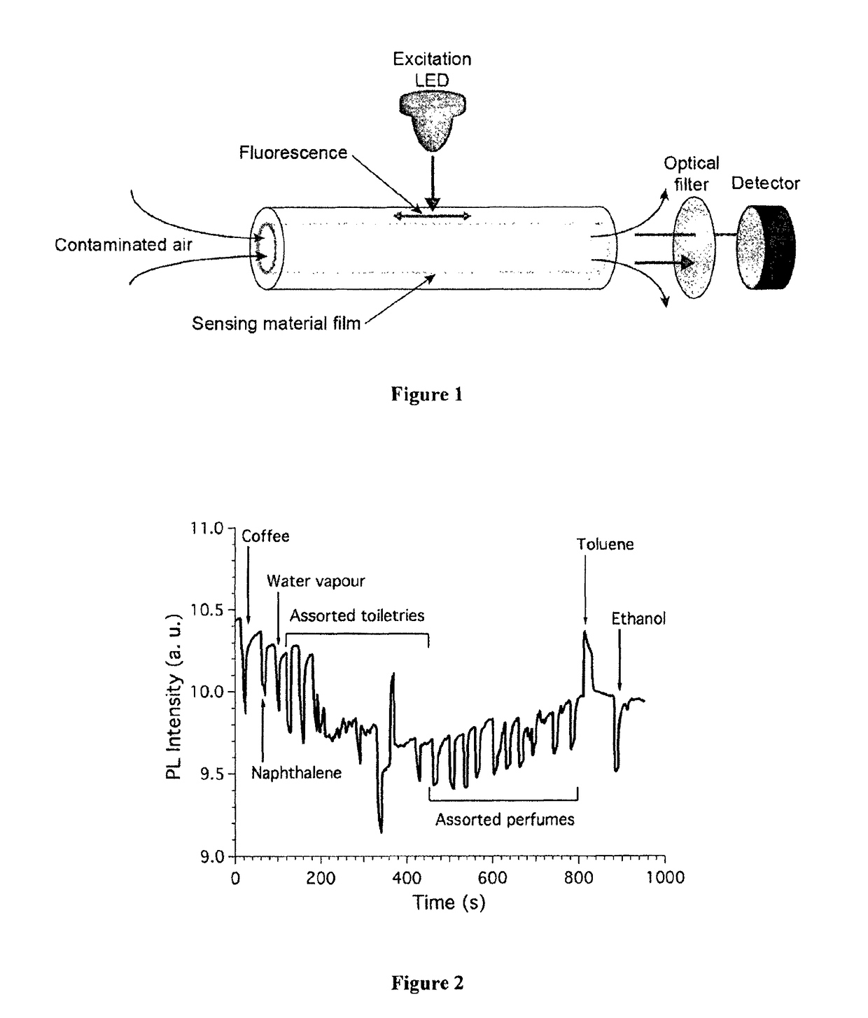
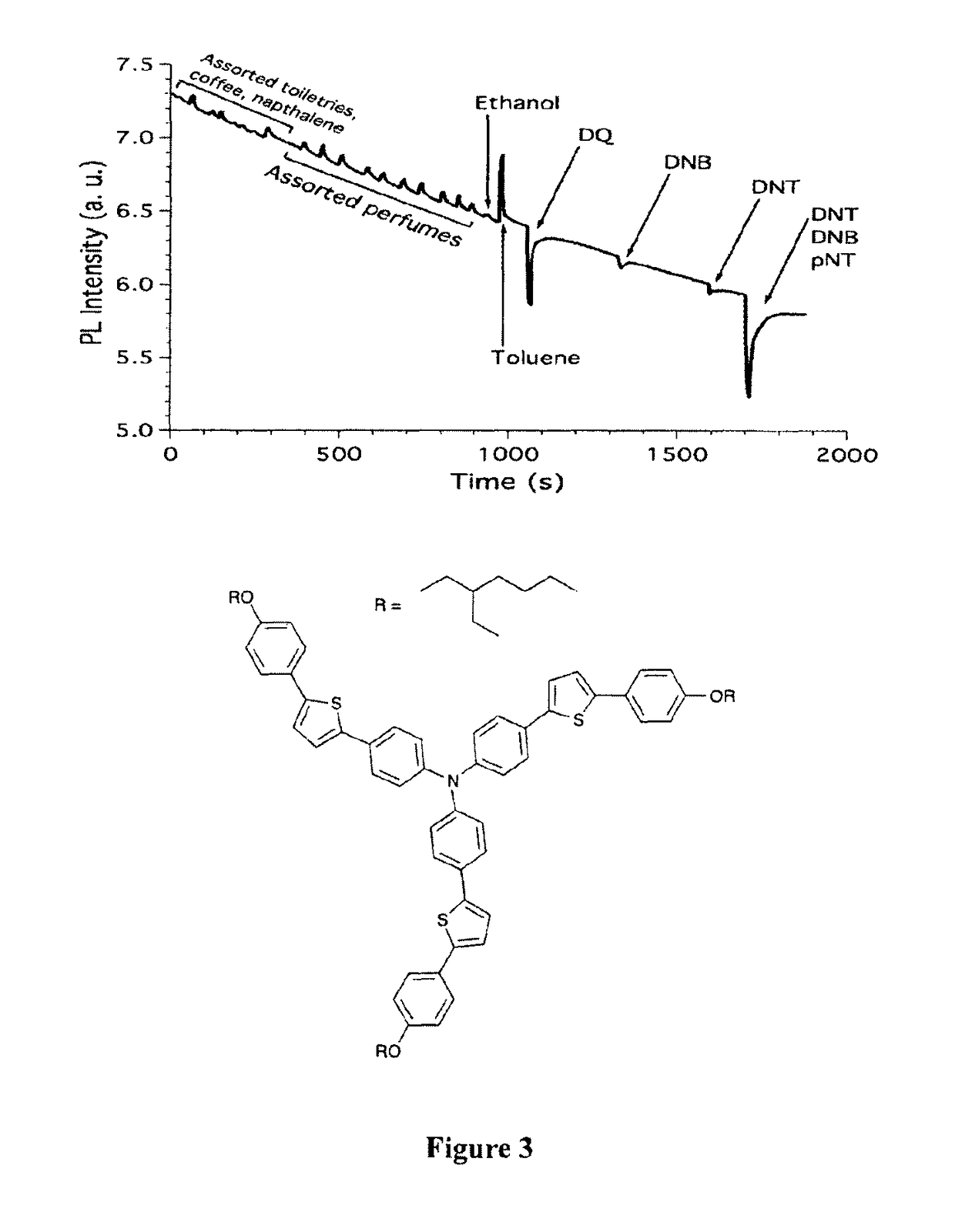
[0101]The channel of a glass capillary with the following dimensions: length=54 mm with the outside diameter=5 mm and internal diameter 0.5 mm, was coated with a triphenylamine centred thiophene-containing compound by blowing a solution of the material in toluene through the capillary with a flow of nitrogen gas. The coated capillary was then exposed sequentially to vapours of a range of everyday chemicals and nitroaromatic compounds (see FIG. 3). Vapour mixtures of species were not used. While exposure to nitroaromatic compounds results in a quenching of the fluorescence signal all the everyday chemicals give an increase in the fluorescence signal. In this way the sensing device shows selectivity.

[0102]In FIG. 3 the X-axis (time) denotes the time from commencement of the experiment at which the device is exposed to a particular species.

example 2

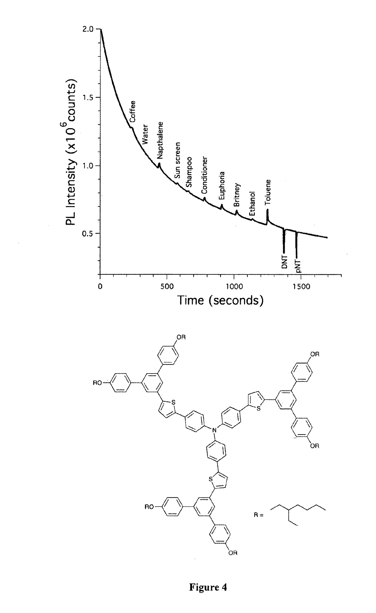
[0103]The channel of a glass capillary as above was coated with a triphenylamine centred thiophene containing dendrimer (FIG. 4) by blowing a solution of the material in toluene through the capillary with a flow of nitrogen gas. The coated capillary was then exposed sequentially to vapours of a range of everyday chemicals and nitroaromatic compounds. As with Example 1 the results show that the dendrimer exhibits an increase in fluorescence signal when exposed to the vapours from a series of everyday chemicals and quenching when it is exposed to the nitroaromatics DNT and pNT. Thus, the modification of the structure, through the addition of dendrons, has not altered the basic sensing properties.

example 3

[0105]The triphenylamine centred fluorene dendrimer shown in FIG. 6 was tested to determine whether the triphenyl amine thiophene combination was necessary for the observed selectivity. Fluorene only-based compounds, such as the one described in Example 2, do not exhibit selectivity. All tests were again performed as in Examples 1, 2, and Comparative Example 2 by coating the inside of the sensing element (glass capillary with the same dimensions as Example 1) with the sensing compound. The results show the same selectivity behaviour as observed with the other triphenylamine-based compounds: only the nitroaromatic compounds show quenching of the fluorescence with everyday chemicals resulting in an increase in the fluorescence signal. The mono-fluorene compound was also found to be more stable to photooxidation than the thiophene-containing compound.


PUM


Abstract

A sensing element for use in the detection of an analyte based on a luminescent response, the sensing element comprising a luminescent triaryl amine compound provided as a coating on a substrate.

Description

[0001]This application is a continuation of U.S. patent application Ser. No. 14 / 649,780 filed 4 Jun. 2015, which is the U.S. national phase of International Application No. PCT / AU2013 / 001410 filed 4 Dec. 2013, which designated the U.S. and claims priority to AU Patent Application No. 2012905287 filed 4 Dec. 2012, the entire contents of each of which are hereby incorporated by reference.FIELD OF THE INVENTION[0002]The present invention relates to the detection of analytes, in particular explosives and explosives-related materials.BACKGROUND TO THE INVENTION[0003]The ability to reliably detect a specific compound even at low concentrations is a continuing challenge, and there is the on-going need to provide new methodologies and devices to do this. The detection of explosives and explosives-related compounds that are commonly used in terrorist attacks and war zones is a particularly pressing need. Although there is often talk of dirty bombs, biological and nuclear terrorism, and impro...

Claims


Application Information

Patent Timeline
Patent Type & Authority Patents(United States)
IPC IPC(8): G01N21/64C07C211/54G01N33/52G01N33/00C07D333/20G01N21/03
CPCG01N21/643C07C211/54C07D333/20G01N21/645G01N33/0057G01N33/52G01N21/6408G01N2021/6482G01N2021/0346G01N2021/6432
Inventor BURN, PAUL LESLIEMEREDITH, PAULSHAW, PAUL EDWARD
Owner THE UNIV OF QUEENSLAND
Learn More