
Model-based definition for machining aircraft parts

a technology for aircraft parts and model-based definitions, applied in the field of aircraft part machining and assembly, can solve the problems of large amount of effort, interference with the hole alignment of the mating component, and the complexity of the design and development of complex 3d geometry models of many modern aircraft component parts, so as to reduce the cost of assembling aircraft structure assemblies, reduce assembly time, and facilitate assembly

Active Publication Date: 2018-12-04
THE BOEING CO
View PDF14 Cites 2 Cited by
  • Summary
  • Abstract
  • Description
  • Claims
  • Application Information

AI Technical Summary

Benefits of technology

The patent describes a method for assembling aircraft structure assemblies that reduces cost and improves quality. The method involves machining parts to nominal specifications, using pre-drilled holes for alignment and assembly without the need for final-hole-size drill jigs. The parts can be easily fitted together at assembly. The method can also allow for the assembly of parts from multiple suppliers without the need for additional tooling or costly shims. The resulting assembly is of higher quality with better part fit. The method also involves sending 3D geometry models for the parts to manufacturing facilities to generate accurate machining programs, and machine the parts to the same mating surface feature profile for a reliable fit during assembly. Overall, this method reduces assembly time, reduces re-work, and reduces assembly costs.

Problems solved by technology

Designing and developing complex 3D geometry models for many modern aircraft component parts is a powerful but expensive and intricate process where component part performance and design constraints are balanced against manufacturing capability and cost.
Manufactures expend large amounts of effort and resources balancing these issues.
For example, in the case of mounting holes centered in two co-planar 1-inch wide flanges that fit alongside of each other, the nominal width dimension is 1.000 inch and the tolerance for the width of the flange should be +0.000 / −0.030 inch since positioning two flanges having a width greater than 1.000 alongside each other would cause the centered mounting holes to be shifted further apart from each other and potentially interfere with hole alignment in a mating component.
This process of manufacturing part features to fall within tolerance ranges also typically results in gaps for shimming component parts at assembly, and an inexact definition of the shape of part details; and the resulting component parts or their assembly is then often forced into shape using multiple large tools during manufacturing.
The use of the aforementioned shimming, as well as the locating fixtures, templates and final-hole-size drill jigs during assembly is costly, and often results in a high-level of nonconformance that must be repaired.
The traditional assembly process also often involves use of multiple shims, which also adds cost and time.

Method used


Image

  • Model-based definition for machining aircraft parts
  • Model-based definition for machining aircraft parts
  • Model-based definition for machining aircraft parts

Examples


Embodiment Construction

[0049]Some implementations of the present disclosure will now be described more fully hereinafter with reference to the accompanying drawings, in which some, but not all implementations of the disclosure are shown. Indeed, various implementations of the disclosure may be embodied in many different forms and should not be construed as limited to the implementations set forth herein; rather, these example implementations are provided so that this disclosure will be thorough and complete, and will fully convey the scope of the disclosure to those skilled in the art. Like reference numerals refer to like elements throughout.

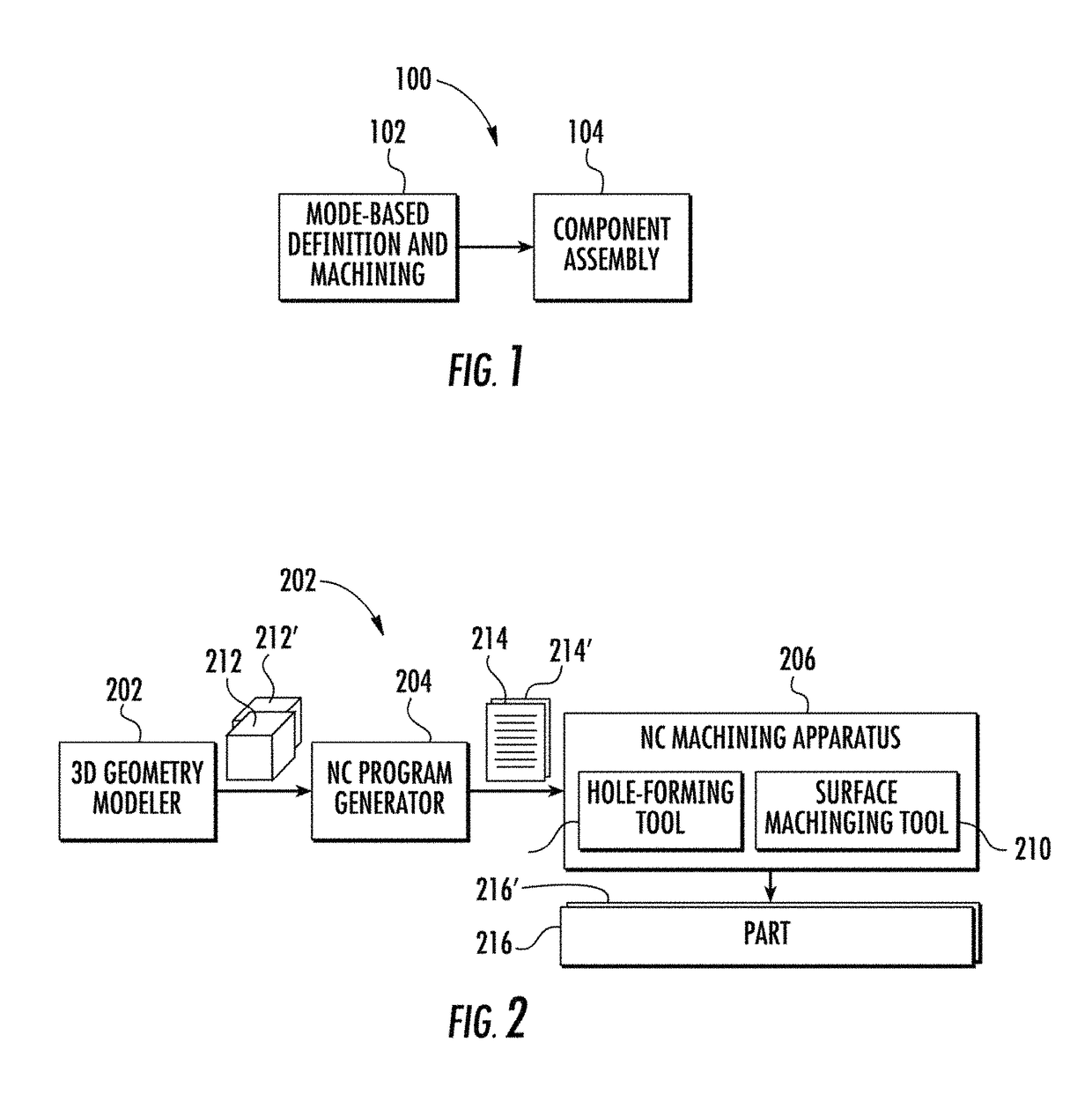
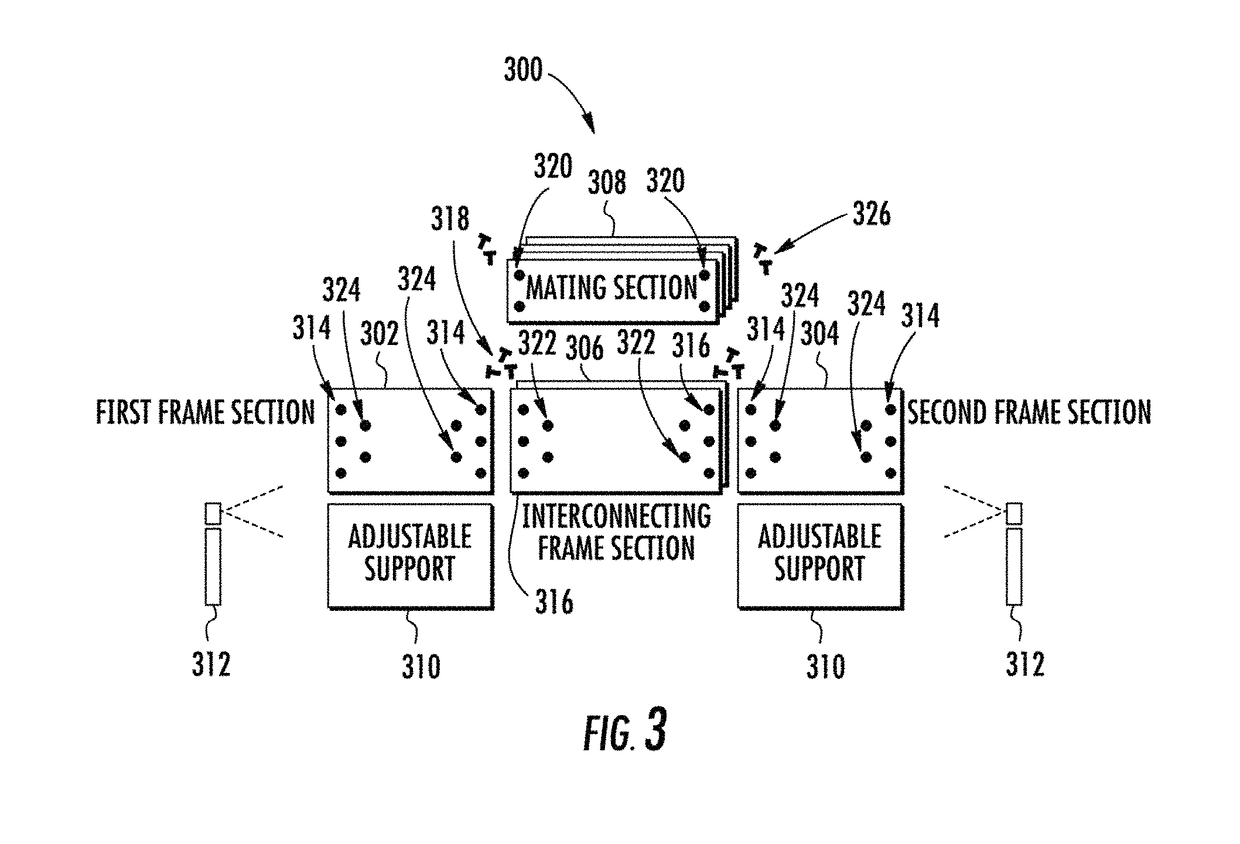
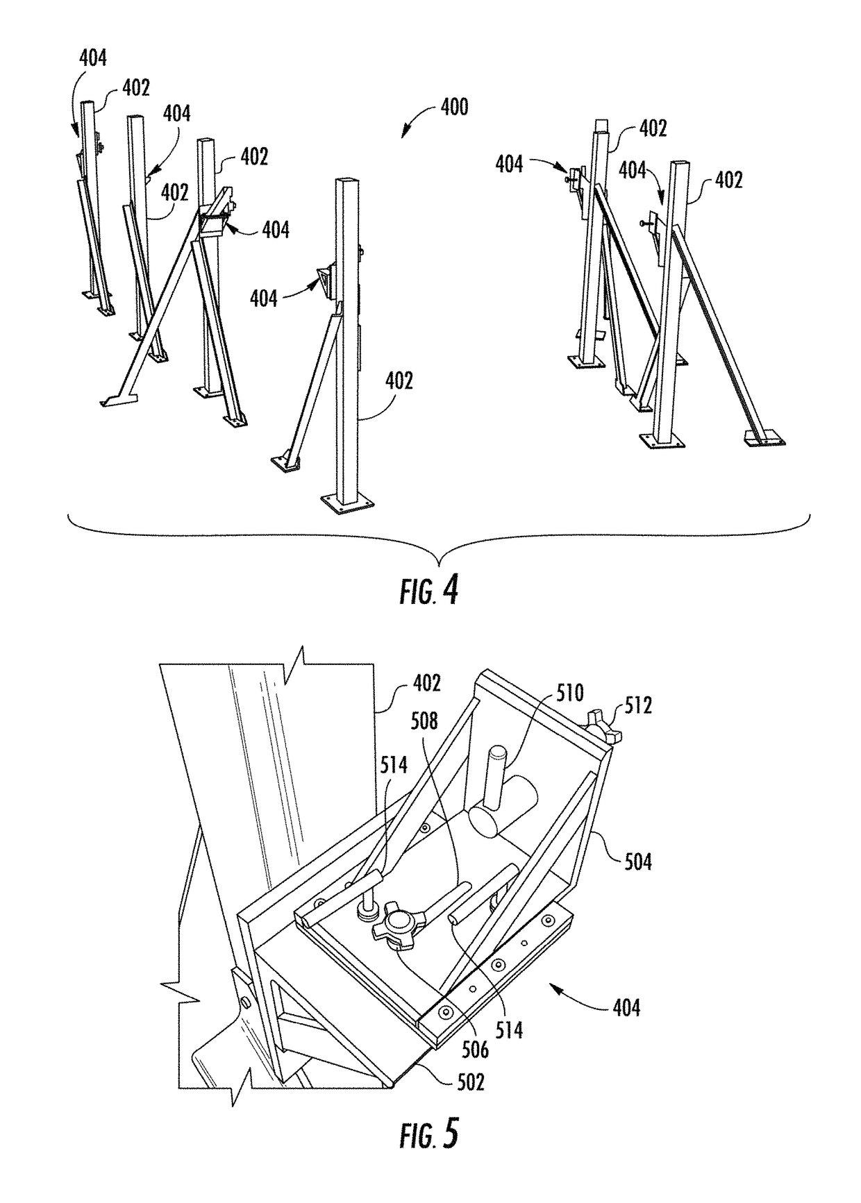
[0050]Example implementations of the present disclosure are generally directed to aircraft part machining and assembly and, in particular, to model-based definition for machining aircraft parts, and assembly of parts without use of any shimming, locating fixtures or final-hole-size drill jigs. FIG. 1 illustrates a system 100 according to example implementations of th...


PUM


Abstract

A method of manufacturing aircraft parts includes creating corresponding 3D geometry models representing surface features and holes of the aircraft parts sized to nominal dimensions. The method includes sending the 3D geometry models to respective manufacturing facilities for each to generate a NC machining program directly from a 3D geometry model, with instructions for a single NC machining apparatus to machine an aircraft part, and including instructions to machine the surface features and / or holes to the modeled dimensions. And for each of the respective manufacturing facilities to machine the aircraft part utilizing the NC machining program. For this, the NC machining apparatus utilizes tool(s) set at substantially the modeled dimensions, instead of at a high or low side of related tolerance range(s) to allow for tight geometric dimensioning and tolerancing requirements. This method enables the full process capability of the CNC machines while utilizing inspection tolerances that are measurable.

Description

CROSS-REFERENCE TO RELATED APPLICATION(S)[0001]The present application is a continuation-in-part of U.S. patent application Ser. No. 15 / 047,278, entitled: Model-Based Definition for Machining Aircraft Parts, filed Feb. 18, 2016, a continuation-in-part of U.S. patent application Ser. No. 14 / 703,425, entitled: Model-Based Definition for Machining Aircraft Parts, filed May 4, 2015, now U.S. Pat. No. 9,857,789, issued Jan. 2, 2018, and related to U.S. patent application Ser. No. 14 / 703,550, entitled: Assembly of an Aircraft Structure Assembly without Shimming, Locating Fixtures or Final-Hole-Size Drill Jigs, filed May 4, 2015, now U.S. Pat. No. 9,925,625, issued Mar. 27, 2018, the contents of all of which are incorporated herein by reference in their entireties.TECHNOLOGICAL FIELD[0002]The present disclosure relates generally to aircraft part machining and assembly and, in particular, to model-based definition for machining aircraft parts.BACKGROUND[0003]Complex manufacturing projects s...

Claims


Application Information

Patent Timeline
IPC IPC(8): B64F5/10B64F5/00G05B19/4097
CPCG05B19/4097B64F5/10B64F5/00G05B2219/35134G06F2217/12G05B19/4099G05B2219/49008B64F5/40G06F2119/18
Inventor ERION, DONALD L.TURNER, DAVID RAYFINCHAMP, TERESA M.
Owner THE BOEING CO
Learn More