Spacer system for reflective insulation

a spacer system and reflective insulation technology, applied in the direction of ducting arrangement, lighting and heating apparatus, heating types, etc., can solve the problems of insufficient insulation and inefficiency, no system in use in private or commercial buildings, air space during installation and r-value compromis

Inactive Publication Date: 2018-11-13
TOMAINI JOHN C
View PDF12 Cites 0 Cited by
  • Summary
  • Abstract
  • Description
  • Claims
  • Application Information

AI Technical Summary

Benefits of technology

[0005]A principle object of the present invention is to provide a system to improve the R value of reflective material used to wrap heating and air conditioning ducts by providing an air space between the reflective material and the duct. It is also an object of the present invention to provide a system to create an air space between the reflective material and air ducts by utilizing spacer material that is non-conductive and lightweight. It is a further object of this invention to utilize spacer material that can be attached to the duct prior to installation of the duct and is rigid, so that the air space keeps its form and is not compromised or compressed during the installation of the duct.
[0009]The materials or substrates of this invention will also insure, by their weight bearing properties, that the air space between the duct and the insulation are not compromised when installing the air duct in an attic space or when hung on hangers because this system is continuous down the length of the air duct giving rigidity to the insulation without compromising the R value.
[0010]Furthermore, the system of this invention provides for a double layer of the materials or substrates prior to wrapping the reflective insulation for when an even higher R value is needed. That is, the spacer material or substrate can be easily applied a second time over the top of the first layer of spacer material or substrate, and could be mechanically fastened to the first spacer on all four sides overlapping a minimum of ⅛″ on the corners to insure a proper air space is maintained, or can even be applied over the first layer of reflective insulation.

Problems solved by technology

Presently, there is no system in use in either private or commercial buildings that provides an air space between the reflective material and the duct that is non-conductive, light in weight, rigid, and is capable of being pre-installed to the duct prior to installing the duct itself.
Other known methods of spacing reflective insulation are inadequate and inefficient and do not allow for any support so the air space during installation and the R-value is compromised.

Method used


Image

  • Spacer system for reflective insulation
  • Spacer system for reflective insulation
  • Spacer system for reflective insulation

Examples


Embodiment Construction

[0016]The preferred embodiments of the present invention will now be described with reference to the FIGS. 1-5 of the drawings. Identical elements in the various figures are designated with the same reference numerals.

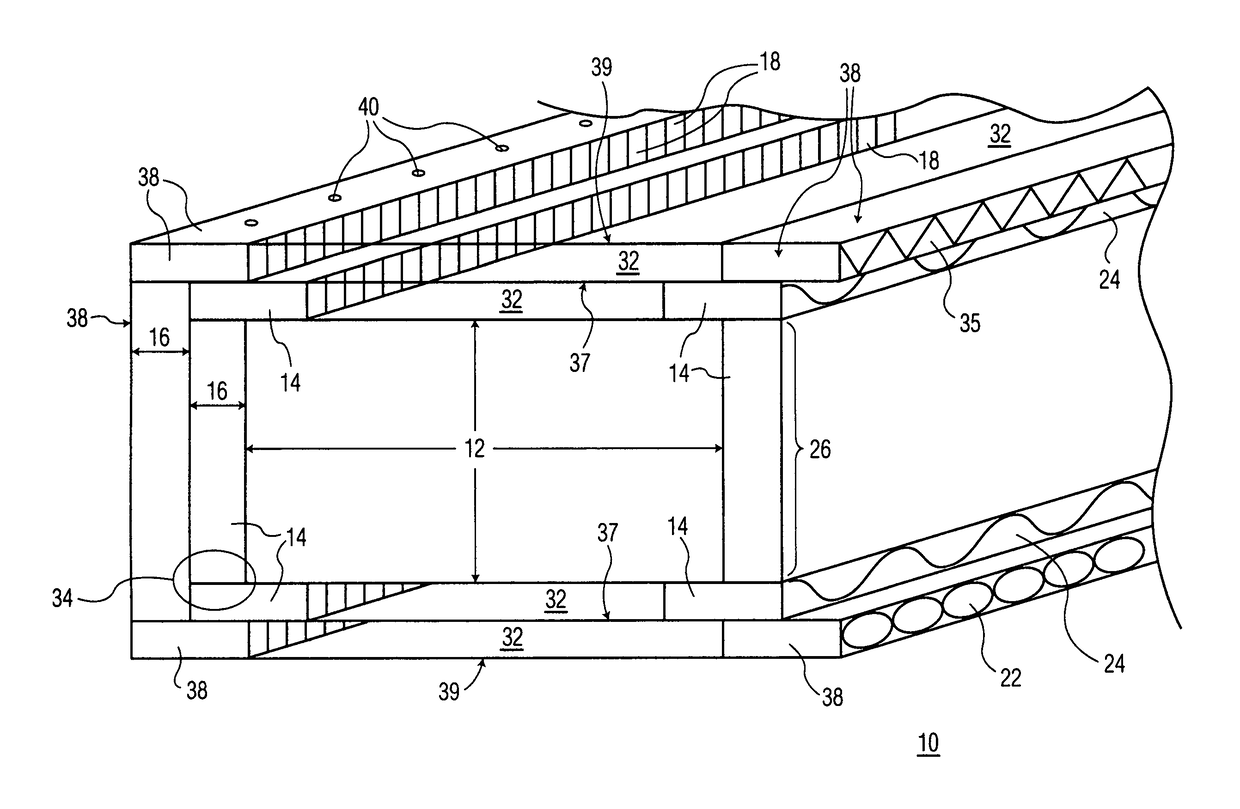
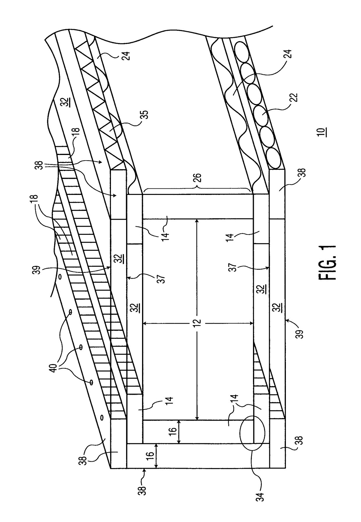
[0017]FIG. 1 illustrates a preferred embodiment of the system of the present invention, generally designated by the reference number 10. The system comprises a ventilation air duct 12 as commonly used in residences, commercial buildings, and the like, for heating and / or cooling, such as in HVAC systems. Traditionally, the ducts are rectangular or square.

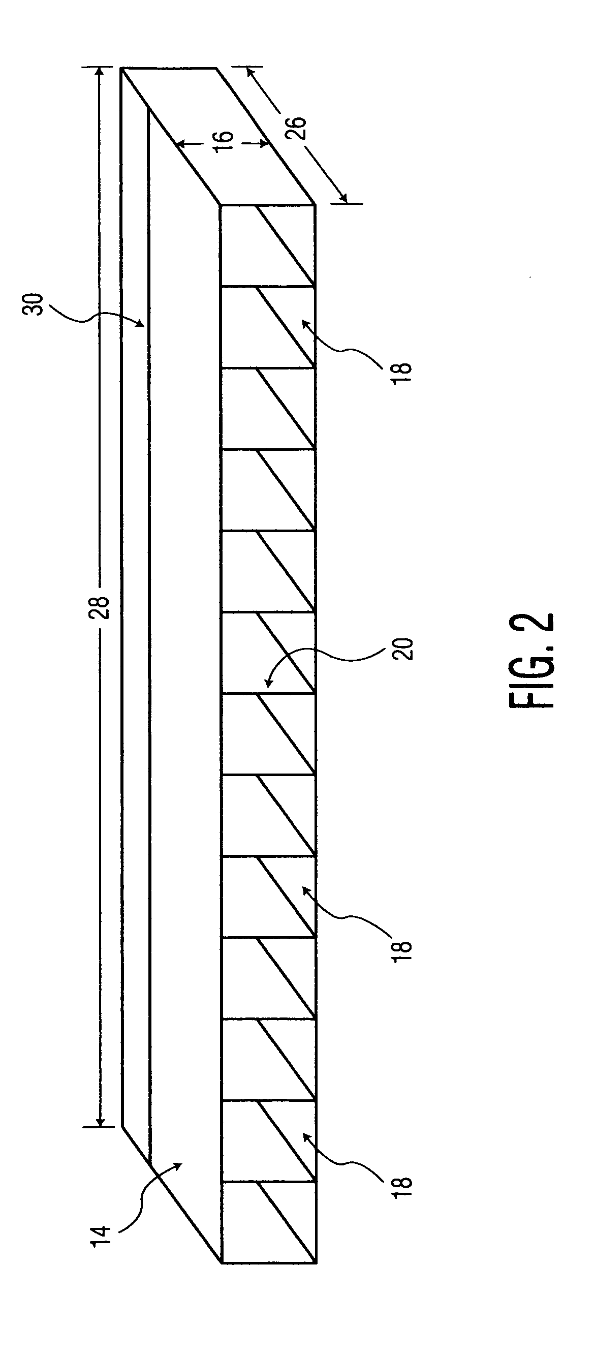
[0018]Connected to the air duct is a first spacer 14, as shown in FIG. 1 as being on the vertical sides and corners of the duct. First spacer 14 is made preferably of a light-weight non heat-conductive material such as stiff paper or cardboard, plastic, Styrofoam, or similar material. Spacer 14 has a thickness 16 that can vary but preferably is a minimum of ⅛ inches up to 1 inch to provide sufficient air space for insul...


PUM


Abstract

A system for providing more efficient insulation for heating and air conditioning ducts is disclosed. Specifically, a system comprising one or more layers of light-weight, rigid spacers made of non-conductive material attached over an air duct, is disclosed. The spacers contain air channels or air spacers, and can be pre-attached to the air duct prior to installation of the duct. The air duct / spacer combination is wrapped with reflective insulation material.

Description

[0001]This application claims priority from U.S. provisional application No. 61 / 402,266 filed Aug. 26, 2010.BACKGROUND OF THE INVENTION[0002]The present invention relates to a system for providing more efficient insulation for heating and air conditioning ducts for a number of uses in the home, apartment buildings or other private or commercial buildings that use HVAC or other similar systems for heating and cooling. In particular, the system according to the present invention provides a more effective and increased R value for reflective insulation that is commonly wrapped around the air conditioning or heating duct.[0003]Reflective insulation, as now used in home and industry to insulate heating and air conditioning ducts, insulates primarily by reflecting radiant energy either to or from the duct. This provides, therefore, an R value based only on the reflective properties of the material. It is well known that air is relatively non-conductive of heat or cold and thus it would be...

Claims


Application Information

Patent Timeline
Patent Type & Authority Patents(United States)
IPC IPC(8): F16L59/07F16L59/02F16L59/08F24F13/02
CPCF16L59/026F24F13/0263F16L59/08F16L59/07
Inventor TOMAINI, JOHN C.
Owner TOMAINI JOHN C
Why Eureka
Try Eureka