
Architecture, system, method, and computer-accessible medium for expedited-compaction for scan power reduction

a scan power and scan power technology, applied in the field of integrated circuit testing, can solve problems such as yield loss, reliability problems, unnecessarily discharging further dynamic power, etc., and achieve the effects of reducing the average test power, simple, scalable, and retaining test data and quality inta

Active Publication Date: 2018-10-23
NEW YORK UNIV IN ABU DHABI CORP
View PDF15 Cites 0 Cited by
  • Summary
  • Abstract
  • Description
  • Claims
  • Application Information

AI Technical Summary

Benefits of technology

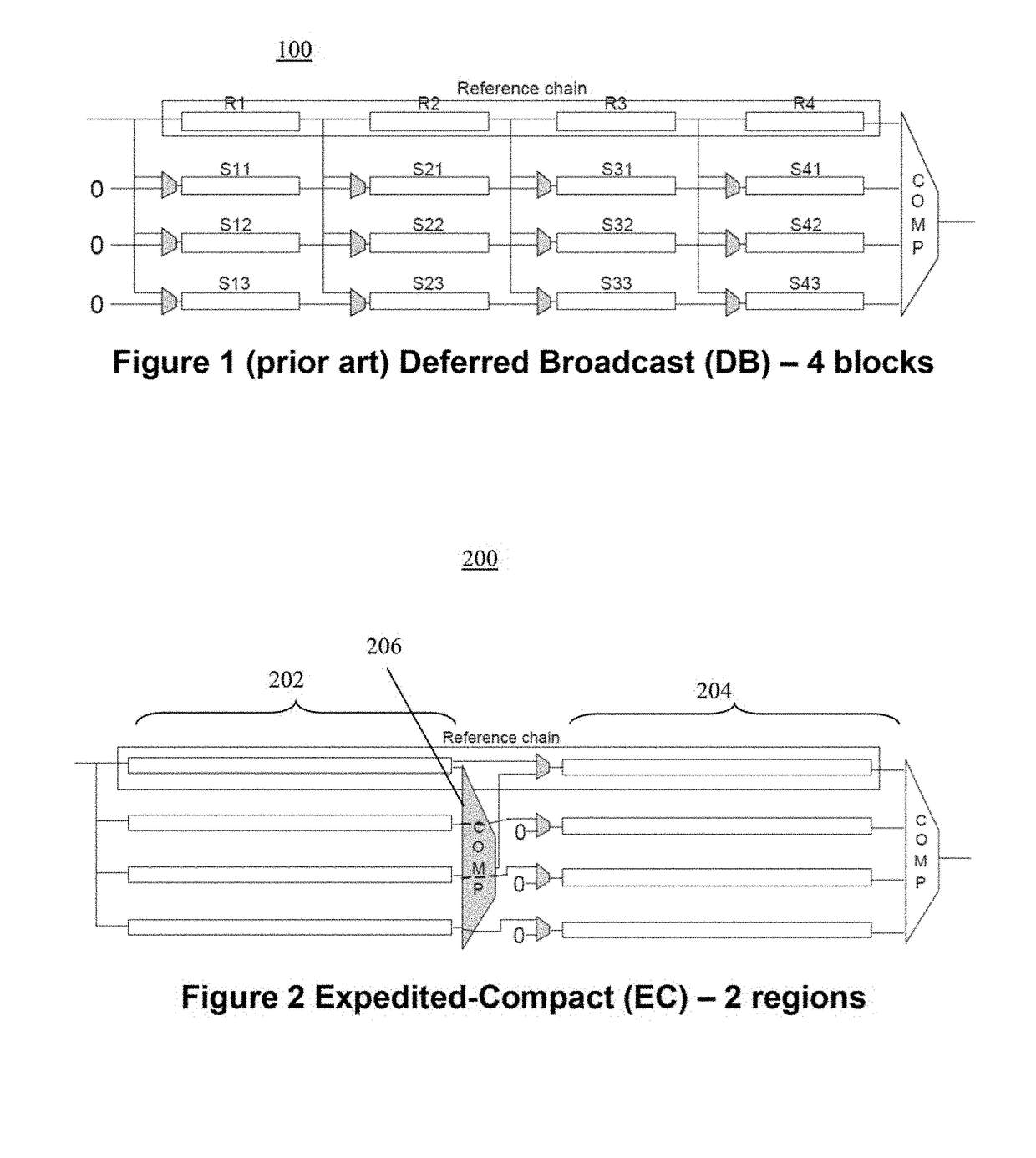
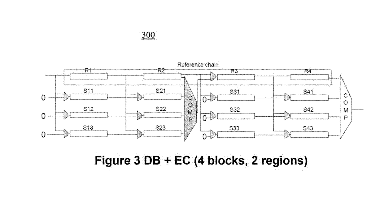
The present disclosure provides a DfT-based architecture that can reduce average test power without resorting to any x-filling techniques. This architecture is simple, scalable, and can retain test data and quality intact. The architecture also facilitates a power-area co-optimization for designs with a tight area budget. The patent also provides a method, apparatus, computer-accessible medium, and device for an expedited response compaction technique and an Expedited-Compact (EC) testing solution to reduce power dissipation during scan operations. The techniques can achieve significant reductions in test power and can be used in conjunction with other complementary approaches. The expidited-compact operations can enable the filling of most of the scan chains with all 0's after a small fraction of the shift operations, delivering scan-out power reductions.

Problems solved by technology

Specifically, serial shift operations during the scan-in of stimulus and the scan-out of response bits can result in a switching activity in the scan chains, which propagate into the combinational logic, dissipating further dynamic power unnecessarily.
An end-result, unless treated properly, could be an unexpected behavior of the design, thereby resulting in a yield loss, or reliability problems.
Elevated levels of peak power, which can be the maximum instantaneous power throughout the entire test process, can be the cause of the former problem, while a reason for the latter problem can be rather average power that is the total power dissipation averaged over the duration of the test application process.

Method used


Image

  • Architecture, system, method, and computer-accessible medium for expedited-compaction for scan power reduction
  • Architecture, system, method, and computer-accessible medium for expedited-compaction for scan power reduction
  • Architecture, system, method, and computer-accessible medium for expedited-compaction for scan power reduction

Examples


Embodiment Construction

[0009]Exemplary embodiments of the present disclosure can provide a DfT-based architecture that can reduce average test power significantly in a cost-effective manner without resorting to any x-filling techniques. The exemplary architecture can be simple, scalable, and may retain test data and quality intact, as observed responses are the same with or without the exemplary Expedited-Compaction (EC). Furthermore, the exemplary EC can be non-intrusive for a design flow, as it does not require clock gating for power savings. The exemplary embodiment of the EC architecture according to an exemplary embodiment of the present disclosure can advance the response compaction operations, ensuring that the reference chain can hold the compacted response during the majority of shift cycles, thus enabling a constant-0 feed into the other chains. The exemplary EC architecture also can facilitate a power-area co-optimization for designs with a tight area budget. Significant reductions in test powe...


PUM


Abstract

Exemplary method, computer-accessible medium, and test configuration can be provided for testing at least one flip-flop. For example, the exemplary test configuration can include at least one scan-out channel having a plurality of regions and a plurality of compactors associated with the plurality of regions. Further, exemplary method, computer-accessible medium, and test configuration can be provided for testing at least on flip-flop that in which at least one scan-out channel having a plurality of regions, a plurality of compactors, and associating the plurality of compactors with the plurality of regions can be provided.

Description

CROSS-REFERENCE TO PRIOR APPLICATION(S)[0001]This application claims priority to U.S. Provisional Application Ser. No. 61 / 446,275, filed on Feb. 24, 2011, which is incorporated by reference herein in its entirety.FIELD OF THE DISCLOSURE[0002]Exemplary embodiments of the present disclosure relate to testing of integrated circuits, and more specifically to an exemplary test architecture, system, method, and computer-readable medium for reduced power consumption for the scan testing of flip-flops.BACKGROUND INFORMATION[0003]Transitions embedded in between consecutive stimulus / response bits toggle scan cells during shift operations. Specifically, serial shift operations during the scan-in of stimulus and the scan-out of response bits can result in a switching activity in the scan chains, which propagate into the combinational logic, dissipating further dynamic power unnecessarily. An end-result, unless treated properly, could be an unexpected behavior of the design, thereby resulting in...

Claims


Application Information

Patent Timeline
Patent Type & Authority Patents(United States)
IPC IPC(8): G01R31/28H03K19/00
CPCH03K19/0008
Inventor SINANOGLU, OZGUR
Owner NEW YORK UNIV IN ABU DHABI CORP
Learn More