Combustor dynamics mitigation

a technology of combustion dynamics and combustion dynamics, which is applied in the direction of combustion process, burners, lighting and heating apparatus, etc., can solve the problems of high cycle fatigue, limiting the operability of gas turbines, and combustion instability/dynamics, and achieve the effect of reducing in-phase and/or coherent combustion dynamics

Active Publication Date: 2018-10-09
GE INFRASTRUCTURE TECH INT LLC
View PDF14 Cites 1 Cited by
  • Summary
  • Abstract
  • Description
  • Claims
  • Application Information

AI Technical Summary

Benefits of technology

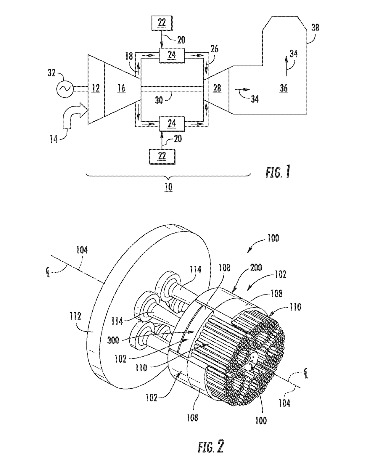
[0008]One embodiment of the present invention is a combustor. The combustor includes a plurality of bundled tube fuel nozzles which are annularly arranged around a common axial centerline. The plurality of bundled tube fuel nozzles comprise a first bundled tube fuel nozzle and a second bundled tube fuel nozzle. The first bundled tube fuel nozzle includes a first fuel plenum and a plurality of premix tubes which extend axially therethrough. The second bundled tube fuel nozzle includes a second fuel plenum and a plurality of premix tubes which extend axially therethrough. The first fuel plenum is axially offset at a predefined axial distance from the second fuel plenum with respect to the common axial centerline so as to mitigate in-phase and / or coherent combustion dynamics within the combustor.
[0009]Another embodiment of the present disclosure is a combustor. The combustor includes an end cover which is coupled to an outer casing. the combustor further includes a plurality of bundled tube fuel nozzles which are annularly arranged around a common axial centerline where each bundled tube fuel nozzle is fluidly connected to the end cover via a fluid conduit which extends downstream from the end cover. The plurality of bundled tube fuel nozzles comprise a first bundled tube fuel nozzle and a second bundled tube fuel nozzle. The first bundled tube fuel nozzle includes a first fuel plenum and a plurality of premix tubes which extend axially therethrough. The second bundled tube fuel nozzle includes a second fuel plenum and a plurality of premix tubes which extend axially therethrough. The plurality of premix tubes of the first bundled tube fuel nozzle includes a first premix tube having a first fuel port which is disposed within the first fuel plenum and a second premix tube having a second fuel port which is disposed within the first fuel plenum. The plurality of premix tubes of the second bundled tube fuel nozzle includes a first premix tube having a first fuel port which is disposed within the second fuel plenum and a second premix tube having a second fuel port which is disposed within the second fuel plenum. The first fuel plenum is axially offset at a predefined axial distance from the second fuel plenum with respect to the common axial centerline so as to mitigate in-phase and / or coherent combustion dynamics within the combustor.
[0010]The present invention also includes a gas turbine. The gas turbine includes a compressor section, a combustion section having a plurality of combustors annularly arranged around an outer casing downstream from the compressor section and a turbine section disposed downstream from the combustors. Each combustor includes an end cover and a plurality of bundled tube fuel nozzles which extend downstream from the end cover. The bundled tube fuel nozzles are annularly arranged around a common axial centerline. The plurality of bundled tube fuel nozzles comprises a first bundled tube fuel nozzle and a second bundled tube fuel nozzle. The first bundled tube fuel nozzle includes a first fuel plenum and a plurality of premix tubes which extend axially therethrough. The second bundled tube fuel nozzle includes a second fuel plenum and a plurality of premix tubes which extend axially therethrough. The first fuel plenum is axially offset at a predefined axial distance from the second fuel plenum with respect to the common axial centerline so as to mitigate in-phase and / or coherent combustion dynamics within the combustor.

Problems solved by technology

Combustion instability / dynamics is a phenomenon which occurs in gas turbines that utilize lean pre-mixed combustion such as those having bundled tube or micro-mixer type fuel nozzles.
In addition, the high frequency dynamic field may excite modes of downstream gas turbine components such as turbine blades, thus potentially contributing to high cycle fatigue.
Such coherent in-phase combustion dynamics can also excite the turbine blades and lead to durability issues, thereby limiting the operability of the gas turbine.

Method used


Image

  • Combustor dynamics mitigation
  • Combustor dynamics mitigation
  • Combustor dynamics mitigation

Examples


Embodiment Construction

[0017]Reference will now be made in detail to present embodiments of the invention, one or more examples of which are illustrated in the accompanying drawings. The detailed description uses numerical and letter designations to refer to features in the drawings. Like or similar designations in the drawings and description have been used to refer to like or similar parts of the invention. As used herein, the terms “first”, “second”, and “third” may be used interchangeably to distinguish one component from another and are not intended to signify location or importance of the individual components. The terms “upstream” and “downstream” refer to the relative direction with respect to fluid flow in a fluid pathway. For example, “upstream” refers to the direction from which the fluid flows, and “downstream” refers to the direction to which the fluid flows.

[0018]Each example is provided by way of explanation of the invention, not limitation of the invention. In fact, it will be apparent to ...


PUM


Abstract

A combustor includes a plurality of bundled tube fuel nozzles which are annularly arranged around a common axial centerline. The plurality of bundled tube fuel nozzles comprise a first bundled tube fuel nozzle and a second bundled tube fuel nozzle. The first bundled tube fuel nozzle includes a first fuel plenum and a plurality of premix tubes which extend axially therethrough. The second bundled tube fuel nozzle includes a second fuel plenum and a plurality of premix tubes which extend axially therethrough. The first fuel plenum is axially offset at a predefined axial distance from the second fuel plenum so as to mitigate combustion tones within the combustor. In one embodiment, premix tube fuel ports disposed within the first and / or second fuel plenums may be axially offset with respect to each other within the corresponding fuel plenums at a predefined axial distance to mitigate combustion tones within the combustor.

Description

FIELD OF THE INVENTION[0001]The present invention generally involves a combustor for a gas turbine. More specifically, the invention relates to a combustor having sectored bundled tube fuel nozzles which is configured to mitigate high and low frequency combustion dynamics within the combustor.BACKGROUND OF THE INVENTION[0002]Gas turbines are widely used in industrial, marine, aircraft and power generation operations. A gas turbine includes a compressor section, a combustion section disposed downstream from the compressor section and a turbine section positioned downstream from the combustion section. The combustion section generally includes multiple combustor cans annularly arranged around an outer casing such as a compressor discharge casing. In particular configurations, each combustor can includes multiple bundled tube or micro-mixer type fuel nozzles annularly arranged around a center fuel nozzle.[0003]Combustion instability / dynamics is a phenomenon which occurs in gas turbines...

Claims


Application Information

Patent Timeline
Patent Type & Authority Patents(United States)
IPC IPC(8): F23R3/28
CPCF23R3/286F23R2900/00014F23D2900/00017
Inventor BETHKE, SVEN GEORG
Owner GE INFRASTRUCTURE TECH INT LLC
Why Eureka
Try Eureka