
Hand held appliance

a technology for hand-held appliances and hand-held devices, which is applied in the direction of electrical apparatus casings/cabinets/drawers, process and machine control, instruments, etc., can solve the problems of motor damage, drop in the temperature of the fluid that exits the hairdryer, electrical failure, etc., and achieves the effect of ensuring repeatability of the positioning of the thermistor, ensuring accuracy of actual temperature measurement, and simplifying manufacturing

Active Publication Date: 2018-10-02
DYSON TECH LTD
View PDF139 Cites 7 Cited by
  • Summary
  • Abstract
  • Description
  • Claims
  • Application Information

AI Technical Summary

Benefits of technology

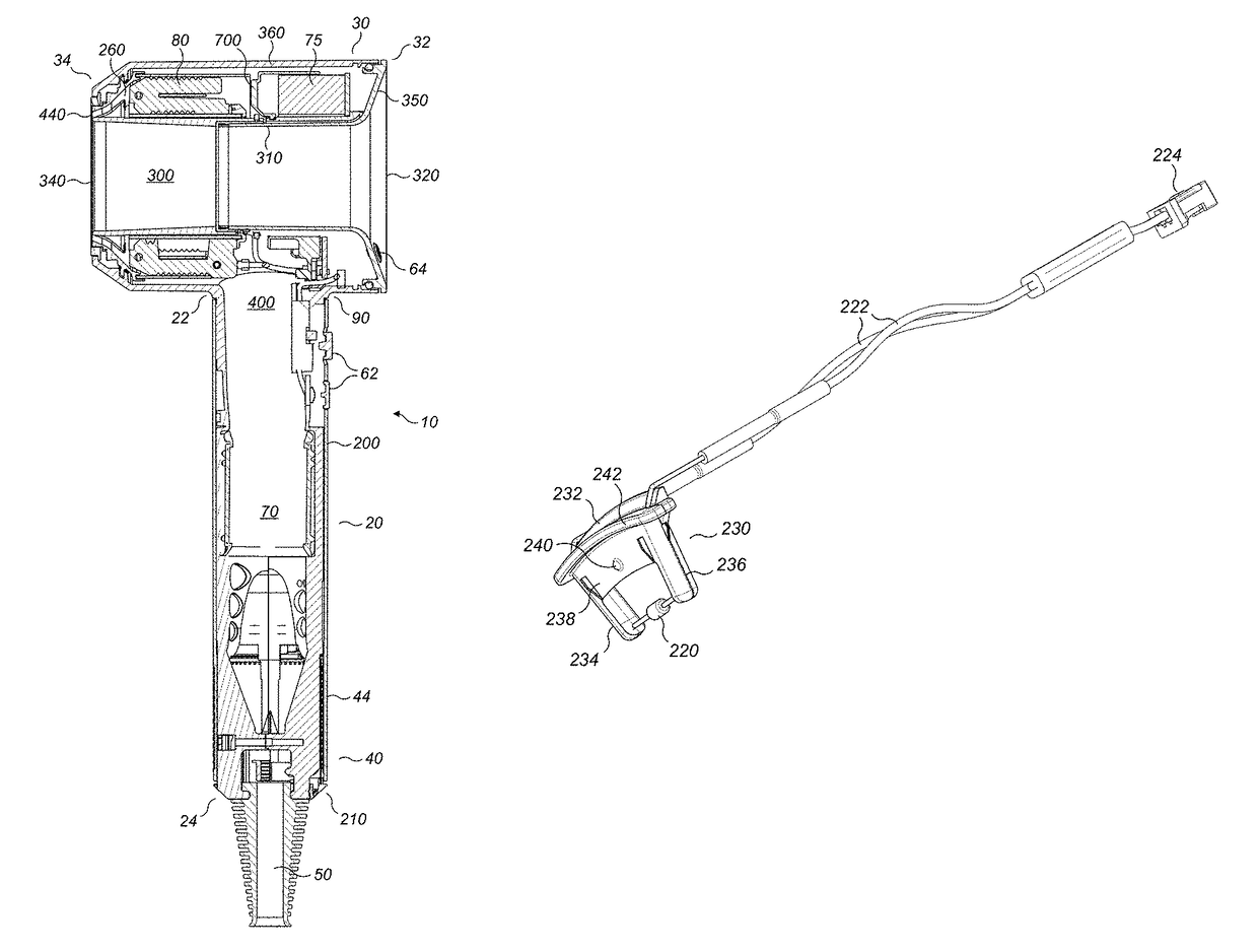
[0011]Preferably, the housing comprises two arms and the thermistor is suspended between the two arms. By suspending the thermistor, it is surrounded by the fluid flow so it is not insulated or shielded from the fluid flow and will therefore give a more accurate measure of the actual temperature.
[0012]It is preferred that the inner wall comprises an aperture into which the housing is inserted. This feature is useful for a number of reasons: manufacture is simplified; and repeatability of the positioning of the thermistor is assured for example.
[0014]It is preferred that the base of the housing comprises a lip which extends radially around the base for engagement with the flange when the housing is positioned correctly with respect to the inner wall. This means that the radial positioning of the thermistor within the heated flow is reliably repeated.
[0027]Preferably, the inner wall comprises at least one channel for accommodating the wiring, the at least one channel extending from an end of the inner wall distal from the fluid outlet. This both locates the wiring in a repeatable and known position and it allows the wiring to be recessed into the inner wall providing a degree of protection during manufacture and assembly and a small space saving.
[0030]It is preferred that the baffle comprises a channel for guiding the wiring along a surface of the baffle. This both locates the wiring in a repeatable and known position and it allows the wiring to be recessed into the inner wall providing a degree of protection during manufacture and assembly and a small space saving.

Problems solved by technology

The motor is susceptible to damage from foreign objects such as dirt or hair so conventionally a filter is provided at the fluid inlet to the blower.
However, if the flow rate is increased there is usually a drop in the temperature of the fluid that exits the hairdryer that can be perceived by the user.
There can be an electrical failure of some sort; alternatively dust and dirt can be pulled into the heater element and if this builds up it can burn and cause an increase in the temperature of the fluid exiting the hairdryer.
Obviously, thermal protection is provided in the form of thermal cut outs such as thermal fuses or bi-metallic strips to prevent an excessive increase in temperature but such protection renders the hairdryer inoperable either temporarily or permanently.

Method used


Image

  • Hand held appliance
  • Hand held appliance
  • Hand held appliance

Examples


Embodiment Construction

[0042]FIGS. 1 and 2 show an example of hairdryer 10 with a handle 20 and a body 30 suitable for use with a thermistor according to the invention. The handle has a first end 22 which is connected to the body 30 and a second end 24 distal from the body 30 and which includes a primary fluid inlet 40. Power is supplied to the hairdryer 10 via a cable 50. At a distal end of the cable 50 from the hairdryer 10 a plug (not shown) is provided, the plug may provide electrical connection to mains power or to a battery pack for example.

[0043]The handle 20 has an outer wall 200 which extends from the body 30 towards a distal end 24 of the handle. At the distal end 24 of the handle an end wall 210 extends across the outer wall 200. The cable 50 enters the hairdryer through this end wall 210. The primary fluid inlet 40 in the handle 20 includes first apertures that extend around and along 42 the outer wall 200 of the handle in a series of rows and / or columns that extend from the distal end 24 of t...


PUM


Abstract

A hair care appliance including a body having an outer wall and an inner wall, a fluid flow path extending from a fluid inlet to a fluid outlet wherein the fluid outlet is at least partially defined by the inner wall, a heater for heating fluid in the fluid flow path and, a thermistor for measuring the temperature of fluid between the heater and the fluid outlet, wherein the thermistor is retained with respect to a housing and the housing forms part of the inner wall. The housing may comprise a base that engages with the inner wall. The housing may further comprise an arm wherein the arm supports the thermistor and extends radially inwards of the inner wall. The housing may comprise two arms and the thermistor is suspended between the two arms. The inner wall may comprise an aperture into which the housing is inserted.

Description

REFERENCE TO RELATED APPLICATIONS[0001]This application claims the priority of United Kingdom Application No. 1518642.2, filed Oct. 21, 2015, the entire contents of which are incorporated herein by reference.FIELD OF THE INVENTION[0002]This invention relates to a handheld appliance and in particular a hair care appliance such as a hairdryer.BACKGROUND OF THE INVENTION[0003]Generally, a motor and fan are provided which draw fluid into a body; the fluid may be heated prior to exiting the body. The motor is susceptible to damage from foreign objects such as dirt or hair so conventionally a filter is provided at the fluid inlet to the blower. The fan and heater require power in order to function and this is provided via internal wiring from either a mains power cable or batteries attached to the appliance.[0004]Conventional hairdryers have control buttons which can change one or more of the flow rate and the temperature of the fluid that exits the hairdryer. However, if the flow rate is...

Claims


Application Information

Patent Timeline
Patent Type & Authority Patents(United States)
IPC IPC(8): A45D20/10H05K5/00G05D23/30H05K7/14
CPCA45D20/10H05K7/1401H05K5/003G05D23/306A45D20/12A45D2200/15
Inventor SAUNDERS, SAMUEL WILLIAMDONALD, GRAHAMBOBILLIER, BEN COLIN
Owner DYSON TECH LTD
Learn More