
Low slip plunger for oil well production operations

Active Publication Date: 2018-08-28
LOSTREETCAR
View PDF11 Cites 3 Cited by
  • Summary
  • Abstract
  • Description
  • Claims
  • Application Information

AI Technical Summary

Benefits of technology

The invention solves problems of plunger slippage and wear in pumps used in oil drilling. By using a plunger that captures produced oil and uses it to slip around the plunger, a tighter seal is formed between the plunger and the barrel, improving pump efficiency and increasing the lifespan of the plunger. The invention also reduces energy usage and increases pumped volumes. Additionally, pump valves reverse during the upstroke, lifting the fluid column and insuring a surplus of oil, which further enhances the longevity of the pump.

Problems solved by technology

Slipping corrosive salt water around a downhole rod pump plunger limits the pump's run life.

Method used


Image

  • Low slip plunger for oil well production operations
  • Low slip plunger for oil well production operations
  • Low slip plunger for oil well production operations

Examples


Embodiment Construction

[0023]The following description may utilize such directional terms as “upper,”“lower,”“inner,”“outer,”“inside,”“outside,” etc. The use of such terms is made with respect to orientation of the figures submitted herewith. However, it is to be understood that such terms may have a different orientation in an actual installation, such that the use of such terms are not to be understood to limit the claimed invention to those particular orientations.

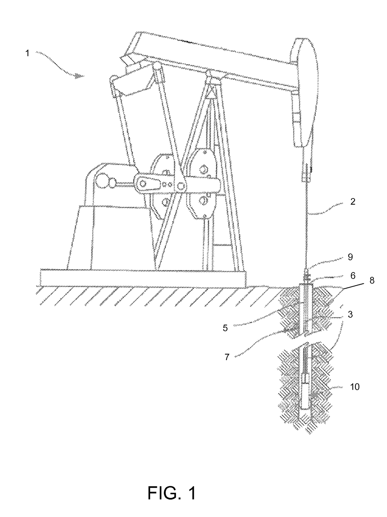
[0024]As can be seen in FIG. 1, in a typical rod pump oil production system, a pumping unit 1 reciprocates a polished rod 2. The polished rod 2 is connected to a plurality of sucker rods 3. The sucker rods 3 are connected to pump 10. Sucker rods 3 are placed concentrically inside tubing 5. Tubing 5 is landed in a wellhead 6. Wellhead 6 is attached to casing 7. Casing 7 is cemented or otherwise sealed in surrounding earth 8.

[0025]The subsurface pump 10 is located in tubing 5 at or near a producing formation. Sucker rods 3 extend from the pump ...


PUM


Abstract

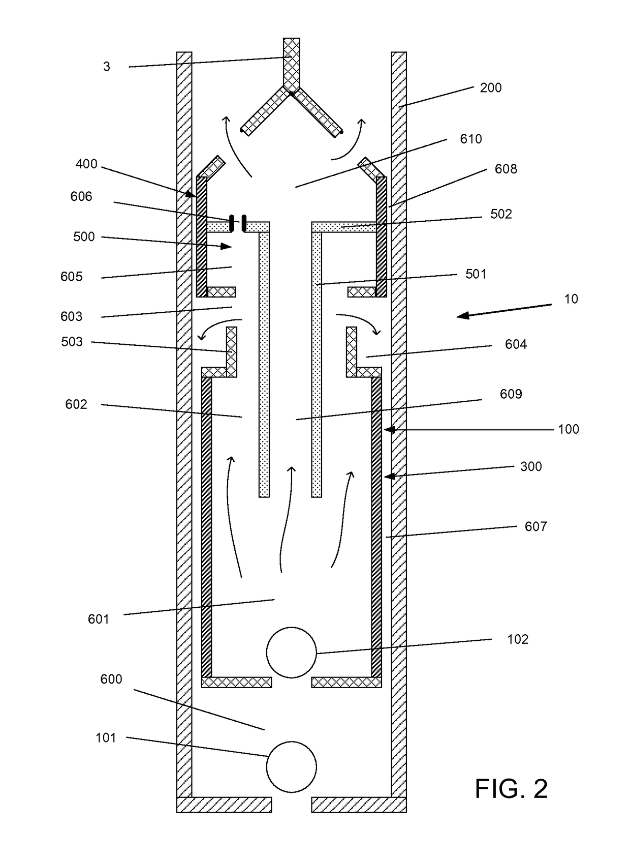
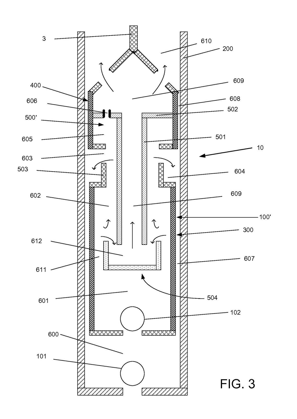
A rod pump plunger is so constructed to collect oil from a produced fluid from an oil well and use it to lubricate the plunger inside of a pump barrel. The plunger has a first sealing structure, a second sealing structure, and penetrating ports in between the sealing structures. A fluid trap which captures oil from the produced fluid flowing through the plunger is formed interior to the body of the plunger and is connected to the port. The trap is connected to a penetrating port such that the trapped oil will flow into the first and second sealing structures. The trap is sized to capture sufficient oil to exceed oil slippage from a pump during each stroke. The oil lubricates the plunger to increase pump efficiency and run life.

Description

FIELD OF THE INVENTION[0001]The present disclosure generally relates to a low slip plunger utilized within a barrel application in oil well production operations which may include use in artificial lift systems for producing at least two phase flow under pressure. One example would be systems flowing oil and water. The most common example would be a subsurface or downhole rod pump deployed in oil and / or gas wells which also produce water.BACKGROUND OF THE INVENTION[0002]Newly drilled petroleum reservoirs often produce oil without water. As they produce over time these reservoirs naturally decline in pressure or start making water. In either case the reservoirs typically require artificial lift to continue producing. Sucker rod pumps deployed in wells that produce oil without water typically produce with higher pump efficiencies and longer pump lives. As reservoirs age they naturally began producing increasing water rates as a result of underground aquifers, waterflooding or changes ...

Claims


Application Information

Patent Timeline
IPC IPC(8): E21B43/12
CPCE21B43/126E21B43/127F04B47/02
Inventor IPPOLITO, JOE J.
Owner LOSTREETCAR
Learn More