Efficient tail gas automatic purifying device

A technology for automatic purification and exhaust gas, applied in chemical instruments and methods, separation of dispersed particles, use of liquid separation agents, etc., can solve the problems of limited effect, separation, and inability to separate solid particles, and achieve the effect of improving the degree of automation

Inactive Publication Date: 2016-07-20
SINOBIOWAY BIOENVIRONMENT CO LTD
View PDF5 Cites 0 Cited by
  • Summary
  • Abstract
  • Description
  • Claims
  • Application Information

AI Technical Summary

Problems solved by technology

When the exhaust gas is directly injected into the water, larger bubbles will be formed. Part of the solid particles contained in the exhaust gas in the bubbles cannot contact with water, so it is difficult to separate them from the exhaust gas. When the bubbles float to the water surface and explode, they return to the exhaust gas. Medium, so the effect is limited
The exhaust gas is washed with water by spraying. Due to the relatively large requirement for spraying water and the gaps between the water droplets, it is impossible to completely separate the solid particles in the exhaust gas when the exhaust gas flow rate is large. , and consumes a lot of water

Method used


Image

  • Efficient tail gas automatic purifying device
  • Efficient tail gas automatic purifying device

Examples


Embodiment Construction

[0028] In order to make the purpose, technical solutions and advantages of the embodiments of the present invention more clear, specific embodiments will be described in detail below with reference to the accompanying drawings.

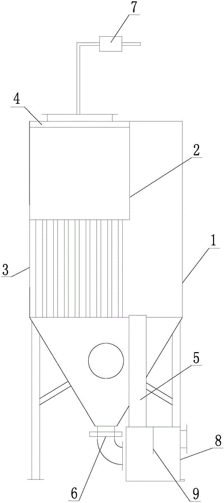
[0029] like figure 1 as shown, figure 1 It is a structural schematic diagram of the present invention. It includes a box body 1, a clapboard 2, a purifier 3, a shower 4, an overflow pipe 5, an impurity sensor, a solenoid valve 6, a controller and a metering pump 7.

[0030] The lower end of the box 1 has a V-shaped structure, and the tip of the V-shaped structure is downward; the purifier 3 is installed in the box 1, and the outer edge of its upper end is connected with the partition 2, which divides the space in the box 1 into spraying The shower chamber, the precipitation chamber and the gas outflow chamber; the spray chamber and the gas outflow chamber are all located above the purifier 3, and the sedimentation chamber is surrounded by a V-shaped...


PUM


Abstract

The invention discloses an efficient tail gas automatic purifying device which comprises a box, partitions, a purifier, a sprayer, an overflow pipe, an impurity sensor, an electromagnetic valve, a controller and a metering pump. A V-shaped structure is arranged at the lower end of the box, a pointed end of the V-shaped structure is downward, the purifier is mounted in the box, the outer edge of the upper end of the purifier is connected with the partitions, a space in the box is divided into a spraying cavity, a precipitating cavity and a gas flowing-out cavity, both the spraying cavity and the gas flowing-out cavity are positioned above the purifier, and the precipitating cavity is formed by surrounding of the V-shaped structure and the purifier and communicated with the gas flowing-out cavity. Multiple purifying holes with axes parallel to each other are formed in the purifier, two ends of each purifying hole are communicated with the spraying cavity and the precipitating cavity respectively, the sprayer is arranged at the top of the box, a gas inlet is formed in the side wall of the box, the overflow pipe is mounted on the box, the first end of the overflow pipe is higher than the second end in position, and height of the first end is greater than that of the lower end face of the purifier. The efficient tail gas automatic purifying device can automatically filter solid particles in tail gas.

Description

technical field [0001] The invention relates to the technical field of waste incineration tail gas treatment, in particular to a high-efficiency tail gas automatic purification device. Background technique [0002] Disposing of municipal solid waste through pyrolysis and gasification is a fast and efficient waste disposal method. However, due to the complex composition of garbage, the exhaust gas contains a large number of solid particles. If discharged directly into the air, it will pollute the air. [0003] In the prior art, the solid particles in the tail gas are separated from the air by directly passing the tail gas into water, or by spraying to make the solid particles in the tail gas wet. When the exhaust gas is directly injected into the water, larger bubbles will be formed. Part of the solid particles contained in the exhaust gas in the bubbles cannot contact with water, so it is difficult to separate them from the exhaust gas. When the bubbles float to the water ...

Claims


Application Information

Patent Timeline
Patent Type & Authority Applications(China)
IPC IPC(8): B01D47/06
CPCB01D47/06
Inventor 李启仁曹文波明永刚舒志强
Owner SINOBIOWAY BIOENVIRONMENT CO LTD
Why Eureka
Try Eureka