
Multi-point sliding door latch

a multi-point, door latch technology, applied in the direction of building locks, constructions, fastening means, etc., can solve the problems of many multi-point sliding door locks that are complex, defeat locks, and require substantial modification, so as to increase security, strengthen attachment, and strengthen the effect of security

Active Publication Date: 2018-08-21
HAUBER PETER
View PDF50 Cites 2 Cited by
  • Summary
  • Abstract
  • Description
  • Claims
  • Application Information

AI Technical Summary

Benefits of technology

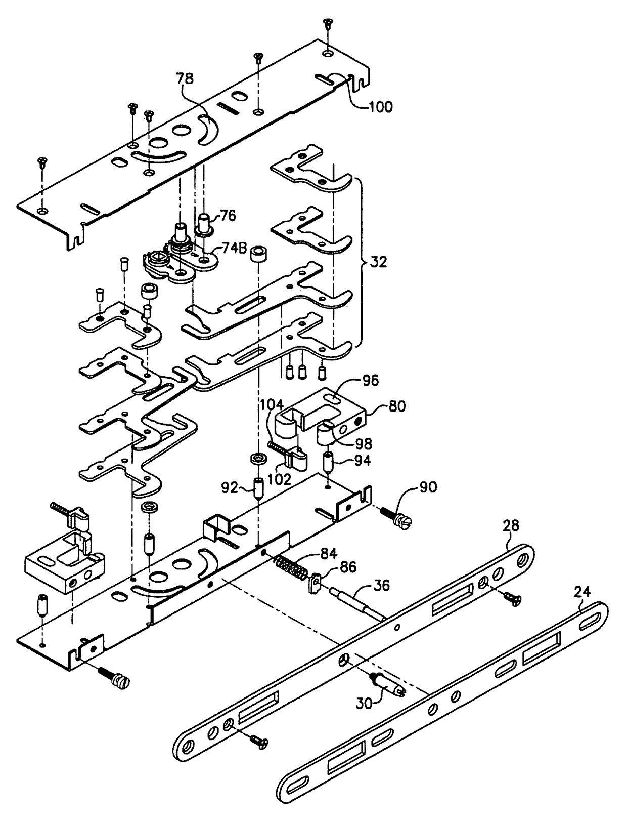
[0006]The present invention provides a lock particularly adapted for increased security against forced entry and heavy doors. The lock provides two points of attachment between the lock and the keeper plate. The attachment means slide rather than rotate allowing for very strong reinforcement of the attachment means which, in turn, allows for a very strong attachment between the lock and the keeper plate. Such strength minimizes the chances of a forced entry accomplished through failure of the lock. Preferably, the attachment means are hooks oriented in opposite directions. Such orientation eliminates the possibility of gaining entry by lifting the hooks out of the opening in the keeper plate by tilting or lifting the door.

Problems solved by technology

Second, if the two hooks are oriented in opposite directions, it precludes the possibility of tilting or lifting the door to disengage the hooks from the keeper plate and thus defeat the lock.
Many multi-point sliding door locks are complex, relatively expensive and require substantial modification of the stile of the sliding door during installation of the lock.

Method used


Image

  • Multi-point sliding door latch
  • Multi-point sliding door latch
  • Multi-point sliding door latch

Examples


Embodiment Construction

[0023]The following description relates only to a preferred embodiment of the invention. The specific features described below do not limit the scope of the invention.

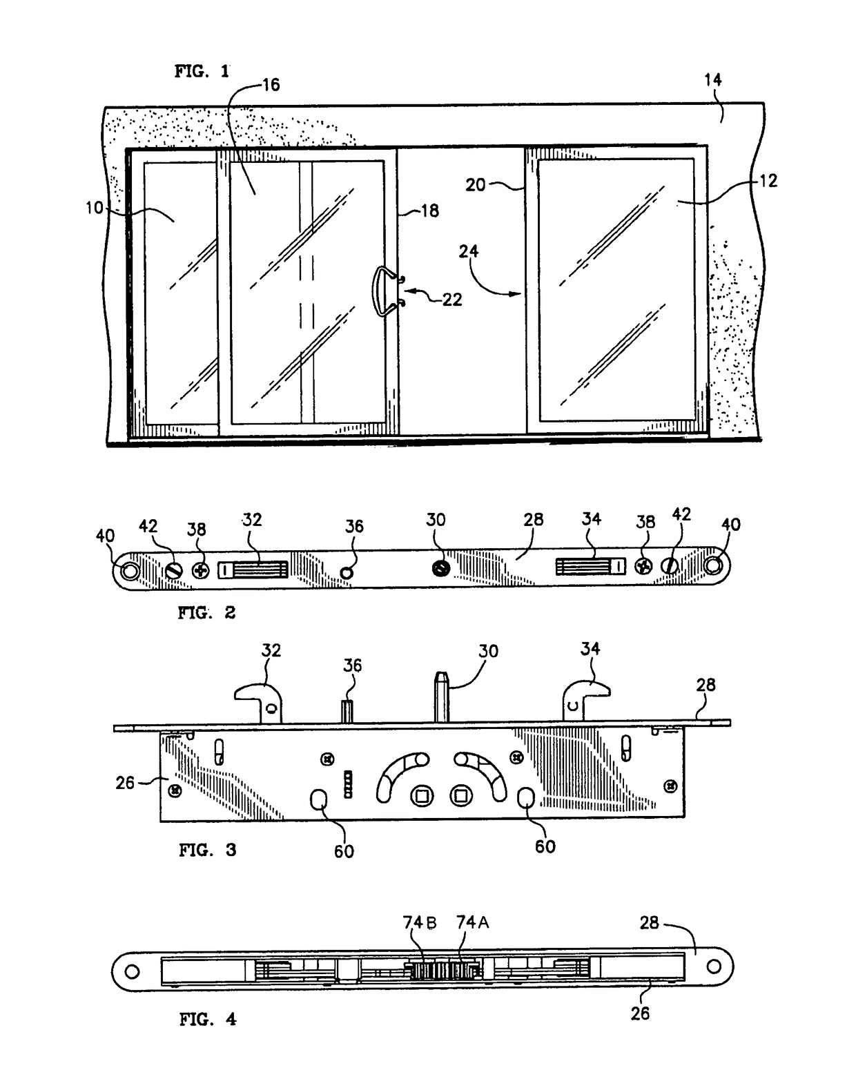
[0024]FIG. 1 shows a typical arrangement for a sliding patio door. Doors 10 and 12 are fixed within an opening in wall 14. Door 16 slides between the open position shown and a closed position in which stile 18 abuts jamb 20. In the closed position, latch 22 within stile 18 contacts keeper plate 24 on jamb 20. Preferably, latch 22 is sized to fit within a standard size opening in stile 18.

[0025]FIG. 11 shows a typical arrangement for mounting latch 22 within an opening of stile 18. Keeper plate 24 is mounted opposite latch 22 on jamb 20 (FIG. 1). Screws 50 pass through holes 40 and secure latch 22 within the opening in the face of stile 18. Door handle 52 is secured to the side of stile 18 by fasteners 54. Fasteners 54 may be screws, bolts or the like and may pass through the entire stile 18 via holes 56 in handle 52, h...


PUM


Abstract

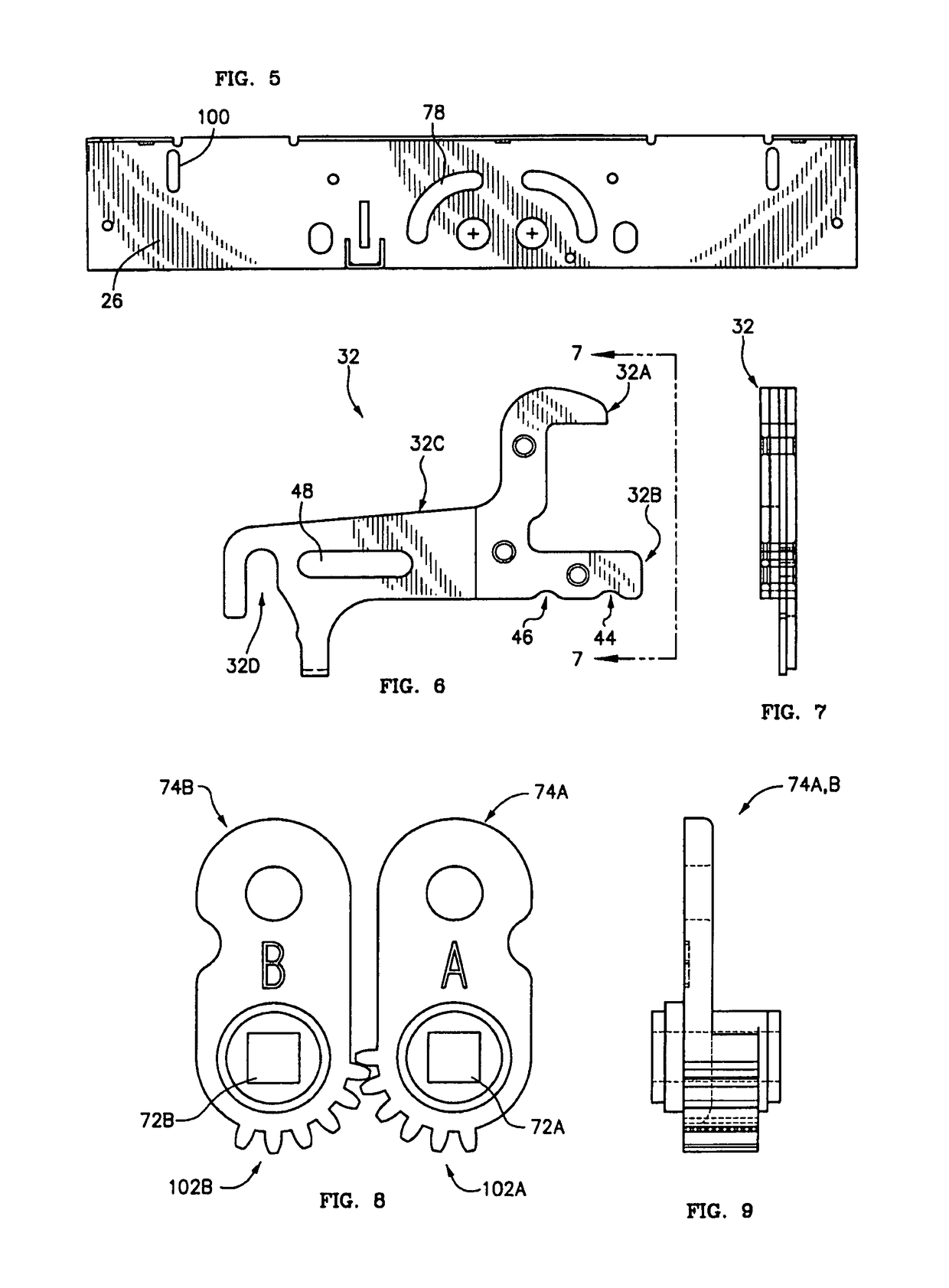
A multi-point sliding door latch intended to fit within standard sized opening in the stile of a sliding door. Preferably the latch has at least two hooks oriented in opposite directions that slide in a generally linear manner between an unlatched and latched position in response to rotation of a pair of actuators located within the latch housing. Preferably, the latch includes reinforcement blocks defining cavities with a portion of the hooks extending into the cavities when the hooks are in the latched position.

Description

CROSS-REFERENCE TO RELATED APPLICATIONS[0001]This is application is a continuation application and claims the benefit of application Ser. No. 13 / 065,499 filed Mar. 22, 2011.BACKGROUND OF THE INVENTION[0002]The present invention relates to multi-point door latches and more particularly to a multi-point door latch particularly suitable for use with sliding doors.[0003]There remains a need for sliding door locks with increased strength and multiple connection points between the sliding door and the corresponding door jamb. The increased strength and multiple connection points reduce the chance of a successful forced entry and allow the lock to be used with relatively heavy doors and in other applications in which the lock may be placed under relatively high tension.[0004]A standard sliding door installation, such as a sliding glass door, typically includes a latch or lock mounted in the face of the stile of the sliding door. Most such locks have a single hook or latching element that i...

Claims


Application Information

Patent Timeline
Patent Type & Authority Patents(United States)
IPC IPC(8): E05C9/16E05C19/12E05C9/00
CPCE05C19/12E05B63/185E05B65/0858E05B65/087E05C5/00E05B15/0053Y10T292/0839Y10T292/0825Y10T292/0829Y10T292/0807Y10T292/0828Y10T292/084
Inventor HAUBER, PETER
Owner HAUBER PETER
Learn More