
Reinforcement device and reinforcement method for heightening support

A reinforcement device and support technology, applied in the direction of bridge reinforcement, erection/assembly of bridges, bridge parts, etc., can solve the problems of baffle deformation, welding reinforcement block restrictions, poor welding quality, etc., to achieve convenient installation and disassembly, reinforcement Strong performance and firm fixation effect

Active Publication Date: 2014-01-15
丰泽智能装备股份有限公司 +1
View PDF6 Cites 0 Cited by
  • Summary
  • Abstract
  • Description
  • Claims
  • Application Information

AI Technical Summary

Problems solved by technology

In order to overcome the above-mentioned defects, the following two methods are mainly used at present: first, the gap between the baffle plate and the upper seat plate is filled with fillers, so that the upper seat plate and the upper slide plate cannot slide, but this method is relatively weak in external force. Hours can play a certain role, but the strength of the baffle cannot be improved. Under the action of a large external force, the baffle will still be deformed and new gaps will be generated, which cannot fundamentally solve the problem; Welding reinforced blocks under the slide plate has the following disadvantages: 1. Due to the different materials of the block and the upper slide plate, the welding quality is poor; 2. Because the upper slide plate outside the block is narrow, the welding of the reinforced block is limited; 3. Set up 4 supports on each pier, the construction space is narrow, especially the internal baffle, the construction is more difficult

Method used


Image

  • Reinforcement device and reinforcement method for heightening support
  • Reinforcement device and reinforcement method for heightening support
  • Reinforcement device and reinforcement method for heightening support

Examples


Embodiment Construction

[0022] The structure of the reinforcement device for the height adjustment support proposed by the present invention will be further described below in conjunction with the accompanying drawings.

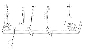
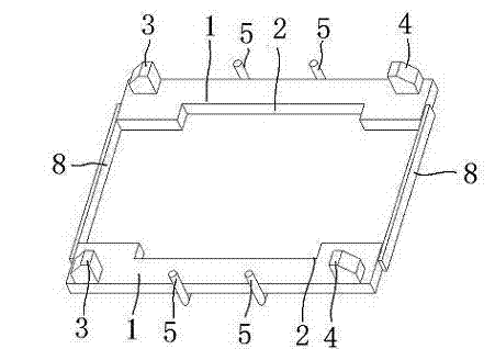
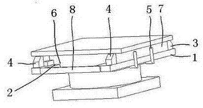
[0023] Such as figure 1 Shown is a structural schematic diagram of the reinforcement device for the height adjustment support. Its structure includes a plate-shaped reinforced body 1. On one side of the reinforced body 1, there are U-shaped slots 2 that can be snapped into the two sides of the upper seat plate of the support. Vertical first fixed block 3 and second fixed block 4, the first fixed block 3 and the second fixed block 4 are located outside the two ends of the upper sliding plate of the height adjustment support. Such as image 3 As shown, the U-shaped card slot 2 of the reinforced body 1 is tightly clamped on both sides of the upper seat plate 6 of the support, and the first fixed block 3 and the second fixed block 4 are tightly clamped on the outer sides of the two en...


PUM


Abstract

The invention belongs to the technical field of support reinforcement devices and reinforcement methods and discloses a reinforcement device and a reinforcement method for a heightening support. The reinforcement device is mainly characterized by comprising a plate-shaped reinforcement body, wherein U-shaped necks clamped in the two side faces of an upper seat plate of the support are arranged on one side of the reinforcement main body, a first fixing block and a second fixing block vertical to the reinforcement main body are respectively arranged on the two ends of the upper surface of the reinforcement main body, the first fixing block and the second fixing block are located on the outer sides of the two ends of an upper sliding plate of the heightening support, the U-shaped necks of the reinforcement main body are firmly clamped on the two side faces of the upper seat plate of the support, and the first fixing block and the second fixing block are firmly clamped on the outer sides of the two end faces of the upper sliding plate. Therefore, the upper sliding plate and the upper seat plate are fixed together through the reinforcement device without generating displacement, the fixing is firmer, the installation and demounting are convenient, the support is convenient to maintain, and the original structure of the support is not damaged.

Description

technical field [0001] The invention belongs to the technical field of a reinforcing device and a reinforcing method for a height-adjusting support, and specifically relates to a reinforcing device for a height-adjusting support and a method for reinforcing with the reinforcing device. Background technique [0002] The height adjustment support is divided into fixed support and one-way sliding support according to the purpose. The fixed support is provided with a baffle under the upper slide plate at both ends of the sliding track of the sliding support. The baffle is easy to deform when the external force is greater than the design value. , A gap is generated between the baffle plate and the upper seat plate, so that a relative displacement occurs between the upper seat plate and the upper slide plate, and the effect of the fixed support cannot be achieved, which affects the structural safety of the beam body. In order to overcome the above-mentioned defects, the following ...

Claims


Application Information

Patent Timeline
Patent Type & Authority Patents(China)
IPC IPC(8): E01D19/04E01D22/00
Inventor 王立志孙向东李炯杨登峰安孝徐瑞祥张培基
Owner 丰泽智能装备股份有限公司
Learn More