
Storage system having a transport system formed by magnetically driven shuttles

Active Publication Date: 2018-07-31
KNAPP AG
View PDF19 Cites 0 Cited by
  • Summary
  • Abstract
  • Description
  • Claims
  • Application Information

AI Technical Summary

Benefits of technology

This patent describes a transport system that allows for independent control of individual shuttles, resulting in more efficient use of energy and prevention of product damage. The system also includes secondary loops that can be used for overtaking or buffering, and allows for increased throughput of products. Additionally, the system design allows for separate loading and unloading of shuttles, simplifying the design of transfer devices.

Problems solved by technology

The known storage system has turned out to be disadvantageous in that the permanent change in the speed of the three conveyor belts on which all products removed from the warehouse and all products to be stored in the warehouse are located will lead to high energy costs associated with the transport system, since large masses have to be decelerated and re-accelerated.
Depending on the shape, weight and position of the products on the conveyor belts, a sudden deceleration or acceleration may cause products to get out of place or topple over on the conveyor belt or even to fall off from the conveyor belt.
As a result, it takes longer for gaps to be created on the conveyor belts, whereby the hauling capacity and the sorting capacity of the known transport system are relatively low.
In addition, the mechanism for synchronizing the conveyor belts with the circular conveyor is cost-intensive and takes up a lot of space because of the large number of individually actuatable conveyor belts.
Said combination is disadvantageous both in terms of space and with regard to the control technology.

Method used


Image

  • Storage system having a transport system formed by magnetically driven shuttles
  • Storage system having a transport system formed by magnetically driven shuttles
  • Storage system having a transport system formed by magnetically driven shuttles

Examples


Embodiment Construction

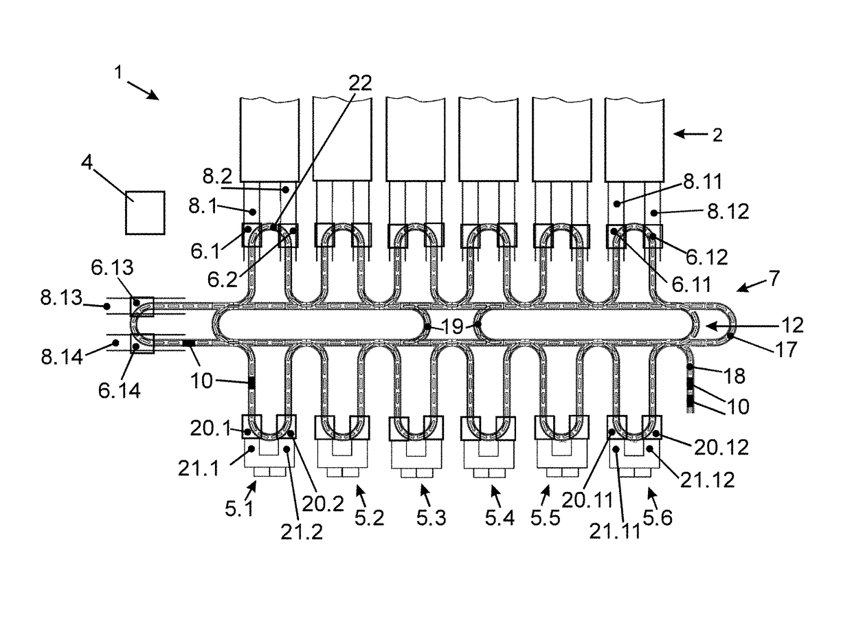
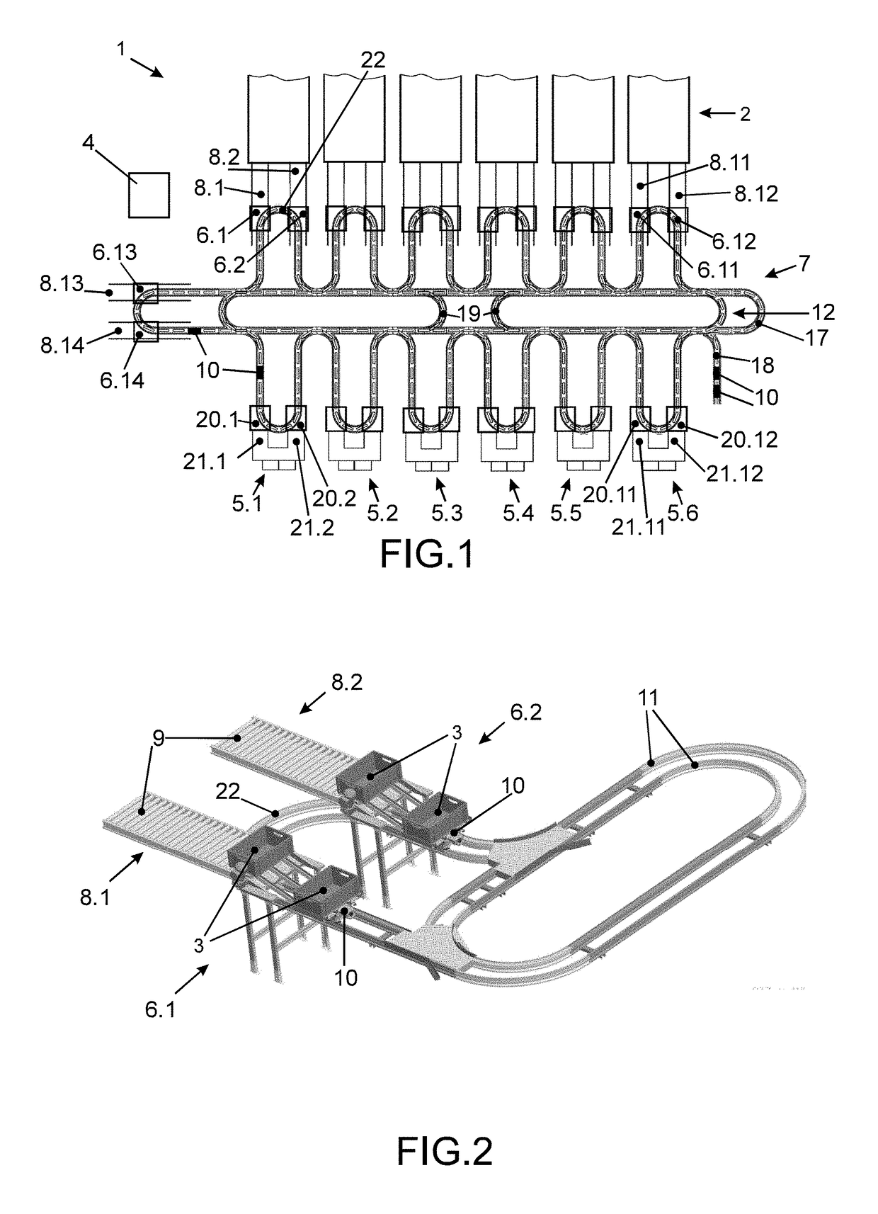
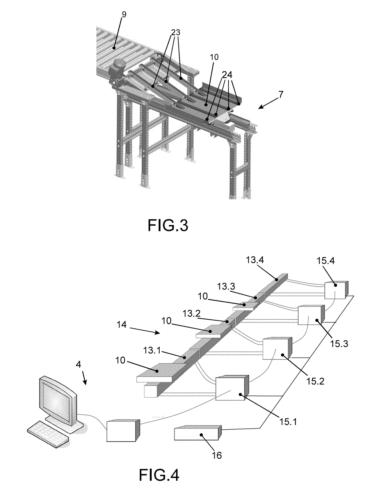
[0019]FIG. 1 shows a storage system 1 with racks 2 for storing products. The racks 2 have several levels and, per level, a plurality of storage sites are provided in which products are stored in boxes 3. A higher-ranking control device 4 manages the products in the storage system 1 and actuates all the facilities described below in order to store products in the storage system 1 and to convey products stored in the storage system 1 to goods-to-picker order-picking stations 5.1 to 5.6. At those goods-to-picker order-picking stations 5.1 to 5.6, pickers remove the number of products as specified for a picking order and put them into an order container.

[0020]In order to convey the products intended for a picking order to the goods-to-picker order-picking station 5.1 to 5.6 intended for the picking order in a sequence as desired for packing the products, the control device 4 removes the products intended for picking from the storage sites of the racks 2 in a particular sequence and tran...


PUM


Abstract

In a storage system with racks for storing products and with a first transfer device for transferring products to be stored in and removed from the racks from a transport system to a rack conveying system and with a second transfer device for transferring products removed from storage which have been transported with the transport system and, respectively, for receiving products to be stored and to be transported with the transport system, it is envisaged that the transport system includes rail-mounted shuttles which are individually controllable with regard to the transport direction and the transport speed and are configured for transporting the products removed from storage and the products to be put into storage between the first transfer device and the second transfer device across rails of at least one main loop.

Description

FIELD OF THE INVENTION[0001]The invention relates to a storage system with racks for storing products and with a first transfer device for transferring products to be stored in and removed from the racks from a transport system to a rack conveying system and with a second transfer device for transferring products removed from storage which have been transported with the transport system and, respectively, for receiving products to be stored and to be transported with the transport system.BACKGROUND OF THE INVENTION[0002]Document EP 1 224 038 B1 discloses such a storage system comprising a transport system for conveying and sorting products removed from the warehouse and products to be stored in the warehouse. The transport system comprises a circular conveyor which forms a main loop and on which the products are transported by means of a continuous member or a conveyor belt, respectively. Products which have been removed from the racks of the storage system are supplied to the circu...

Claims


Application Information

Patent Timeline
IPC IPC(8): B65G1/06B65G1/137
CPCB65G1/065B65G1/1378
Inventor SCHNABL, ROMANKOHOLKA, ROLAND
Owner KNAPP AG
Learn More