
Jet-powered oar system for a paddle board

a technology of jet-powered oars and paddle boards, which is applied in the direction of marine propulsion, special-purpose vessels, vessel construction, etc., can solve the problems of physically painful to move the affected limbs, impede the ability of paddle-powered paddle-powered boards, and virtually impossible to control paddle-powered boards

Active Publication Date: 2018-07-10
AJELLO MIKE
View PDF4 Cites 9 Cited by
  • Summary
  • Abstract
  • Description
  • Claims
  • Application Information

AI Technical Summary

Benefits of technology

The present invention is a jet-powered oar system that can be retrofitted onto a conventional paddle board. It uses an electrically powered impeller pump assembly to propel the paddle board without physical input from the paddler. The system includes a propulsive oar with an oar shaft, oar paddle, impeller pump assembly, primary battery pack, kill switch, and attachment collar. The oar paddle is connected to the oar shaft and positioned below the water line. The attachment collar prevents the propulsive oar from detaching from the paddle board. The invention allows paddles to travel faster and more easily, and can help paddles escape from dangerous situations. It is a self-powered propulsion system that can be used in paddlesport and other water sports.

Problems solved by technology

The fact that paddle boarding exercises the body and allows paddlers to travel vast distances also causes problems.
It is also possible that paddlers may encounter an unexpected emergency that hinders their ability to physically propel the paddle board.
For example, muscle cramps make it physically painful to move the effected limbs.
Nature is another unpredictable element that can prevent the paddler from reaching the desired destination.
Thunderstorms can generate turbulent waves that make it virtually impossible to control the paddle board.
This can cause the paddleboard to capsize and put the paddler in life-threatening situations.

Method used


Image

  • Jet-powered oar system for a paddle board
  • Jet-powered oar system for a paddle board
  • Jet-powered oar system for a paddle board

Examples


Embodiment Construction

[0014]All illustrations of the drawings are for the purpose of describing selected versions of the present invention and are not intended to limit the scope of the present invention.

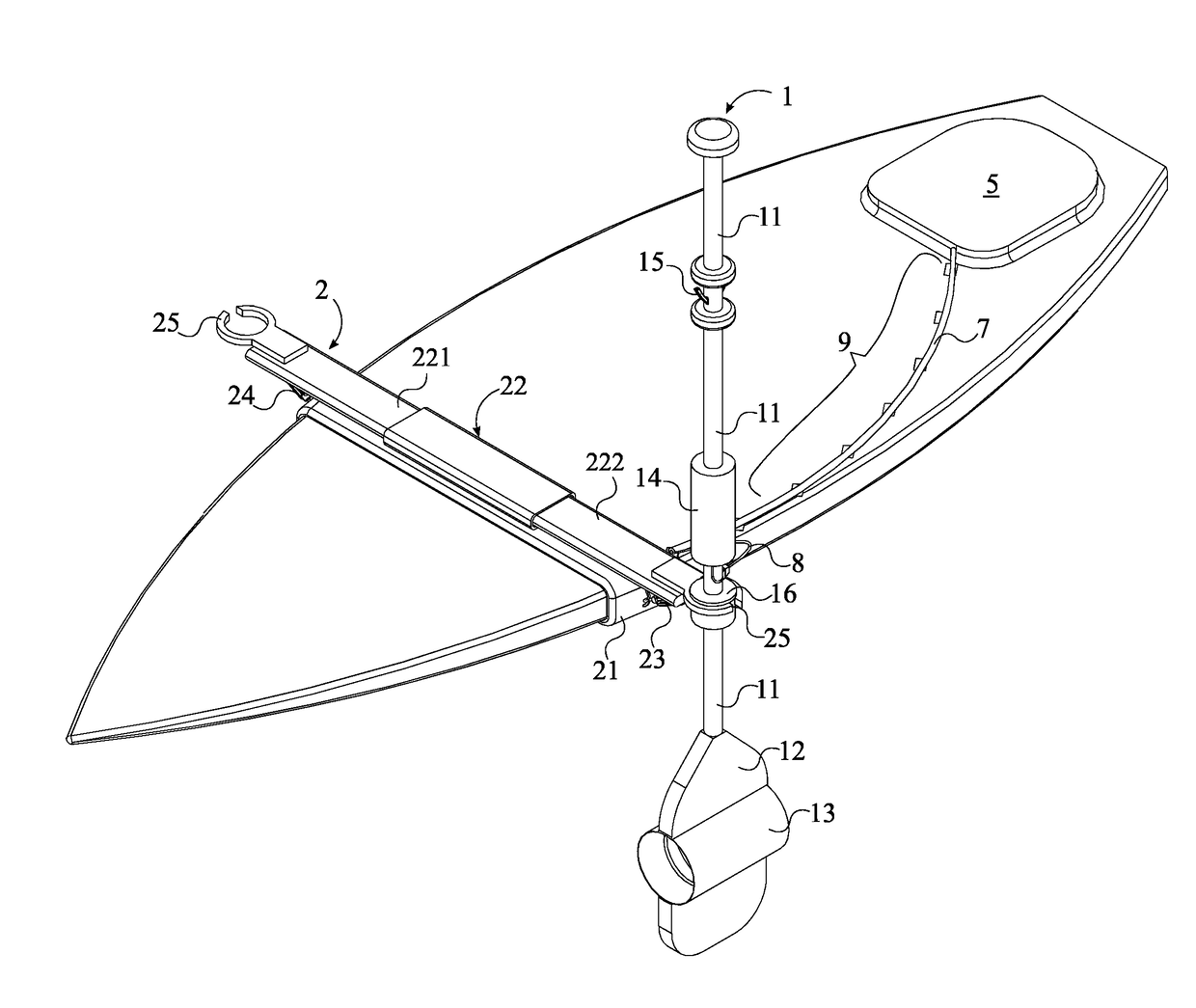
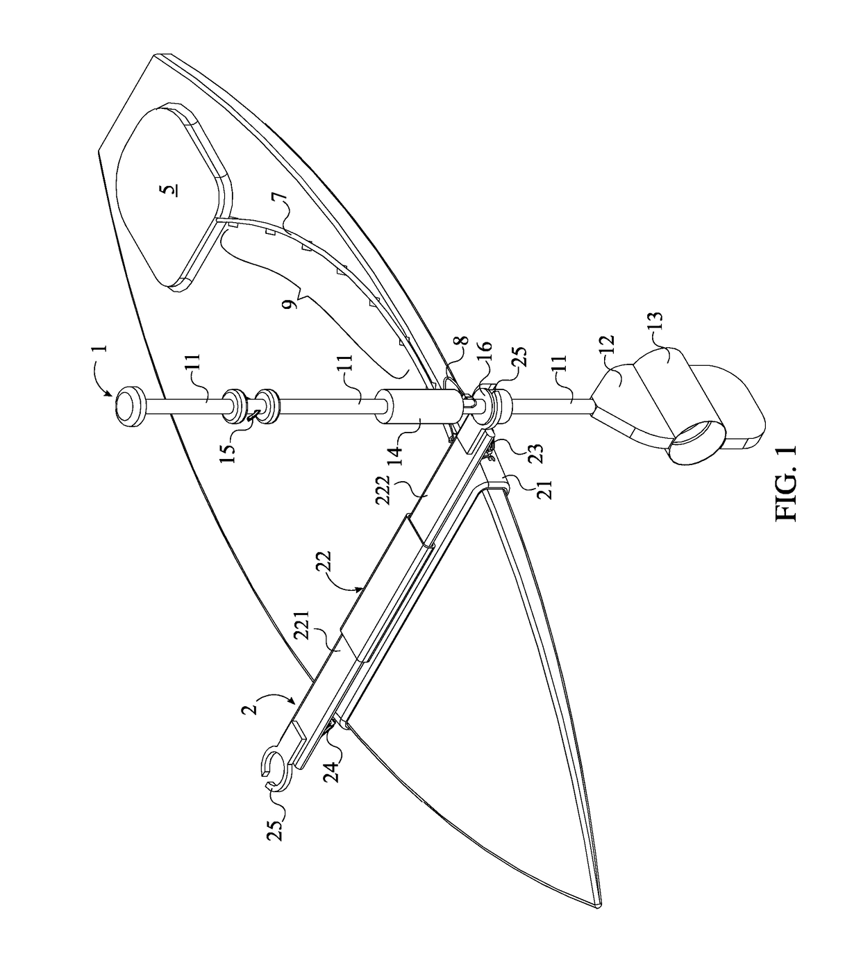
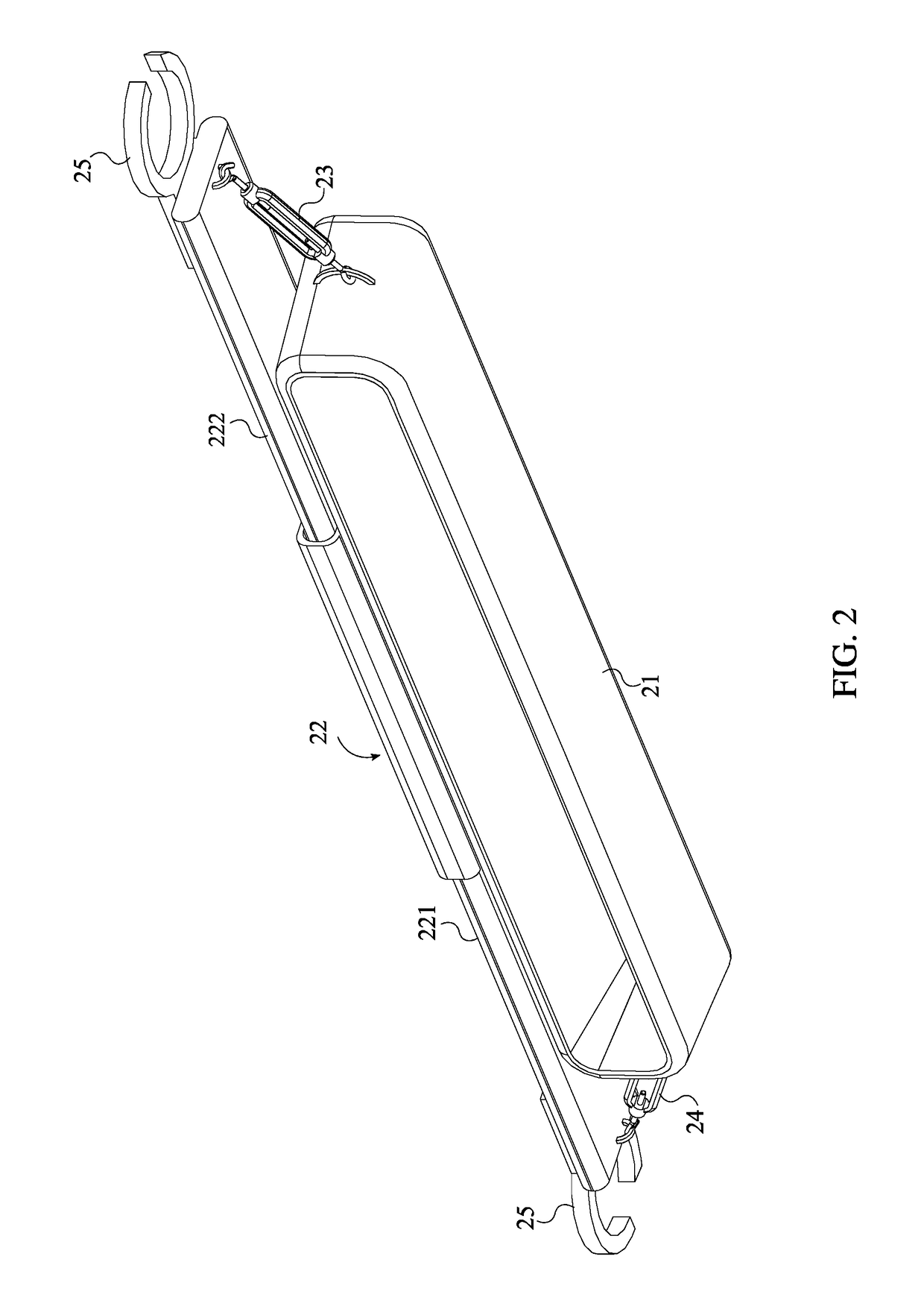
[0015]In reference to FIG. 1, the present invention relates to a jet-powered oar system that is retrofittable onto a conventional paddle board. The preferred embodiment of the present invention comprises a propulsive oar 1 and a restraining mechanism 2. The restraining mechanism 2 selectively mounts the propulsive oar 1 to a conventional paddle board. The propulsive oar 1 uses an electrically powered propulsion system that propels the paddle board without physical input from the paddler. Alternately, the paddler can detach the propulsive oar 1 from the restraining mechanism 2 and use the propulsive oar 1 to physically propel the paddle board.

[0016]In reference to FIG. 3, the propulsive oar 1 further comprises an oar shaft 11, an oar paddle 12, an impeller pump assembly 13, a primary battery pack 14, a ki...


PUM


Abstract

A jet-powered oar system for a paddleboard designed to help paddle boarders travel long distances without feeling fatigue includes a propulsive oar and a restraining mechanism. The propulsive oar propels the paddle board without physical input from the paddle boarder. The restraining mechanism retrofits onto an existing paddleboard and retains the propulsive oar. The propulsive oar utilizes an oar shaft, an oar paddle, an impeller pump assembly, a primary battery pack, a kill switch, and an attachment collar. The oar shaft and the oar paddle can be used to physically propel the paddle board. The impeller pump assembly permits motorized propulsion of the paddle board when the paddle boarder succumbs to fatigue. The primary battery back stores electrical energy for powering the impeller pump assembly. The kill switch stops the paddle board from moving. Finally, the attachment collar couples the propulsive oar onto the restraining mechanism.

Description

[0001]The current application claims a priority to the U.S. Provisional Patent application Ser. No. 62 / 361,834 filed on Jul. 13, 2016.FIELD OF THE INVENTION[0002]The present invention generally relates to jet-powered oar system for a paddle board. More specifically, the present invention comprises a propulsive oar, an impeller pump assembly integrated into the propulsive oar for generating forward thrust, and a restraining mechanism that retrofits onto an existing paddle board and secures the propulsive oar to the paddle board.BACKGROUND OF THE INVENTION[0003]Paddle boarding is a growing sport that provides a unique mix of physical exercise and a recreational experience. Paddle boarding allows paddlers to travel vast distance and experience the natural beauty of waterways such as rivers and oceans. Conventional paddleboards require paddlers to physically propel the paddleboards using oars. This can be used to exercise the body, build strong arms, and promote cardiovascular health.[0...

Claims


Application Information

Patent Timeline
Patent Type & Authority Patents(United States)
IPC IPC(8): B63H11/08B63H16/04B63B35/79
CPCB63H11/08B63H16/04B63H2011/081B63B35/79B63H5/14B63H25/42B63B32/10B63B32/70B63B32/40B63H5/125
Inventor AJELLO, MIKE
Owner AJELLO MIKE
Learn More