


Quick Research
Generate reliable direction feasibility study reports for your R&D in just a few steps.

Technical Q&A
Discover and master advanced knowledge NOW. Basics, ideas, possibilities, all at once.

Find Solutions
As an expert in R&D theories, this can generate solutions to your technical problems instantly.

Evaluate Feasibility
Analyze your overall solution with one click, know your potential R&D risks in advance.

Monitor Landscape
Get weekly tech updates, stay abreast of the latest tech innovations and key insights.
Floating-point complex multiplier
A technology of floating-point complex numbers and multipliers, applied in instruments, machine execution devices, electrical digital data processing, etc., can solve the problems of poor flexibility, high price, large volume and power consumption, etc., to improve data processing speed, volume power The effect of low power consumption and high reliability
- Summary
- Abstract
- Description
- Claims
- Application Information
AI Technical Summary
Problems solved by technology
Method used
Image


Examples
Embodiment Construction
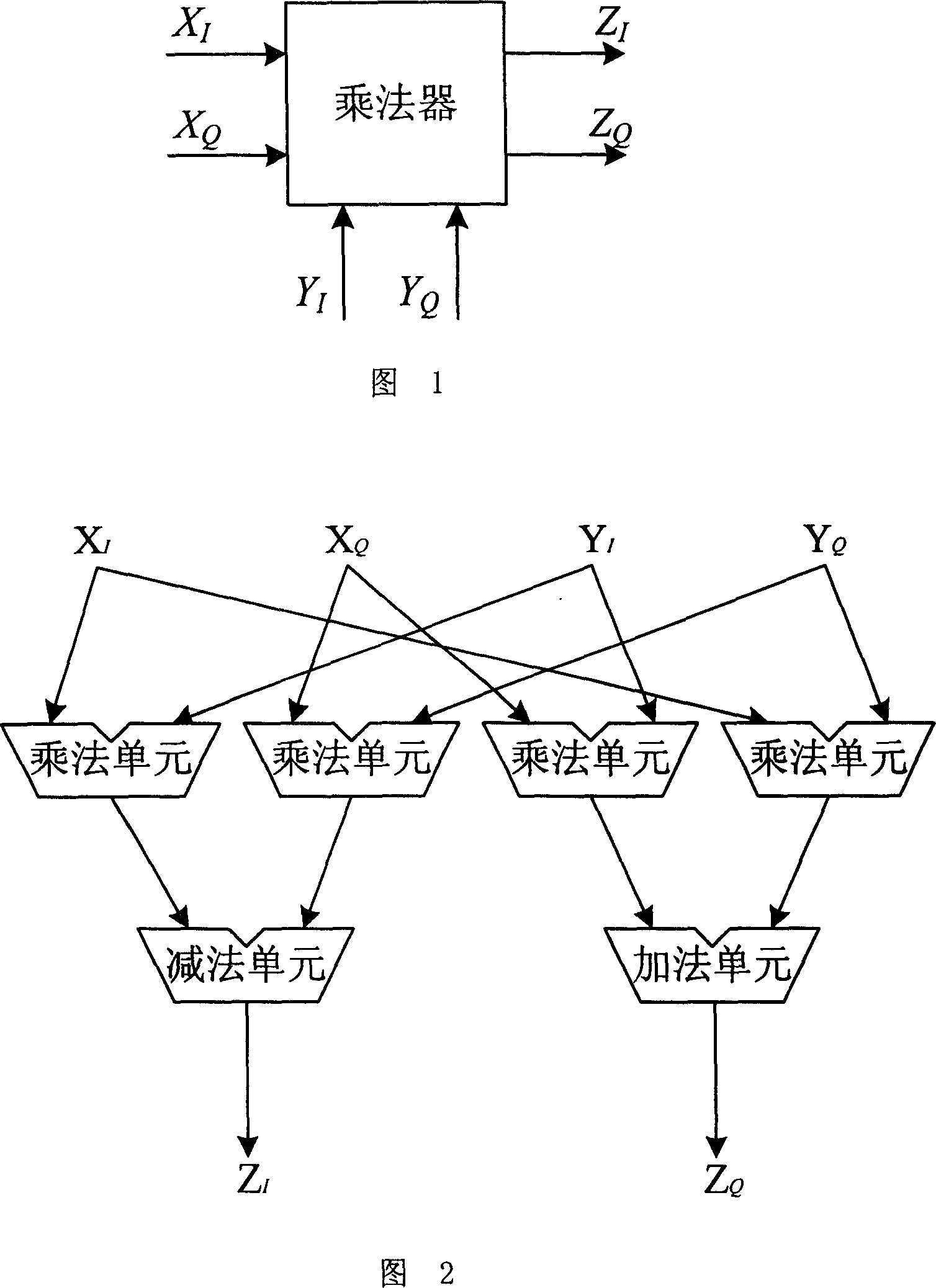
[0022] The embodiment of the floating-point complex multiplier of the present invention includes a data interface, a floating-point addition unit, a floating-point subtraction unit, and four floating-point multiplication units.
[0023] As shown in Figure 1, the data interface includes: the real part (X 1 , Y 1 ) and the imaginary part (X Q , Y Q ), the real part (Z) of the result complex number (Z) 1 ) and the imaginary part (Z Q ) Two output interfaces; the input and output data format conforms to the 32-bit single-precision data format of the IEEE-754 standard.
[0024] As shown in Figure 2, the embodiment of the floating-point complex multiplier of the present invention adopts a two-stage pipeline structure, and consists of four floating-point multiplication float_mul modules, one floating-point addition float_add module and one floating-point subtraction float_sub module. The four floating-point multiply units are:
[0025] Used to combine the real part of two compl...
PUM
 Abstract
Description
Claims
Application Information
 - R&D Engineer
- R&D Manager
- IP Professional
- Industry Leading Data Capabilities
- Powerful AI technology
- Patent DNA Extraction
Browse by: Latest US Patents, China's latest patents, Technical Efficacy Thesaurus, Application Domain, Technology Topic, Popular Technical Reports.
© 2024 PatSnap. All rights reserved.Legal|Privacy policy|Modern Slavery Act Transparency Statement|Sitemap|About US| Contact US: help@patsnap.com