Liquid discharge head and method of manufacturing liquid discharge head
A technology of a liquid discharge head and a manufacturing method, which can be applied to semiconductor devices, electrical solid devices, printing, etc., and can solve problems such as damage and exposure of electrical connections.
- Summary
- Abstract
- Description
- Claims
- Application Information
AI Technical Summary
Problems solved by technology
Method used
Image
Examples
Embodiment 1
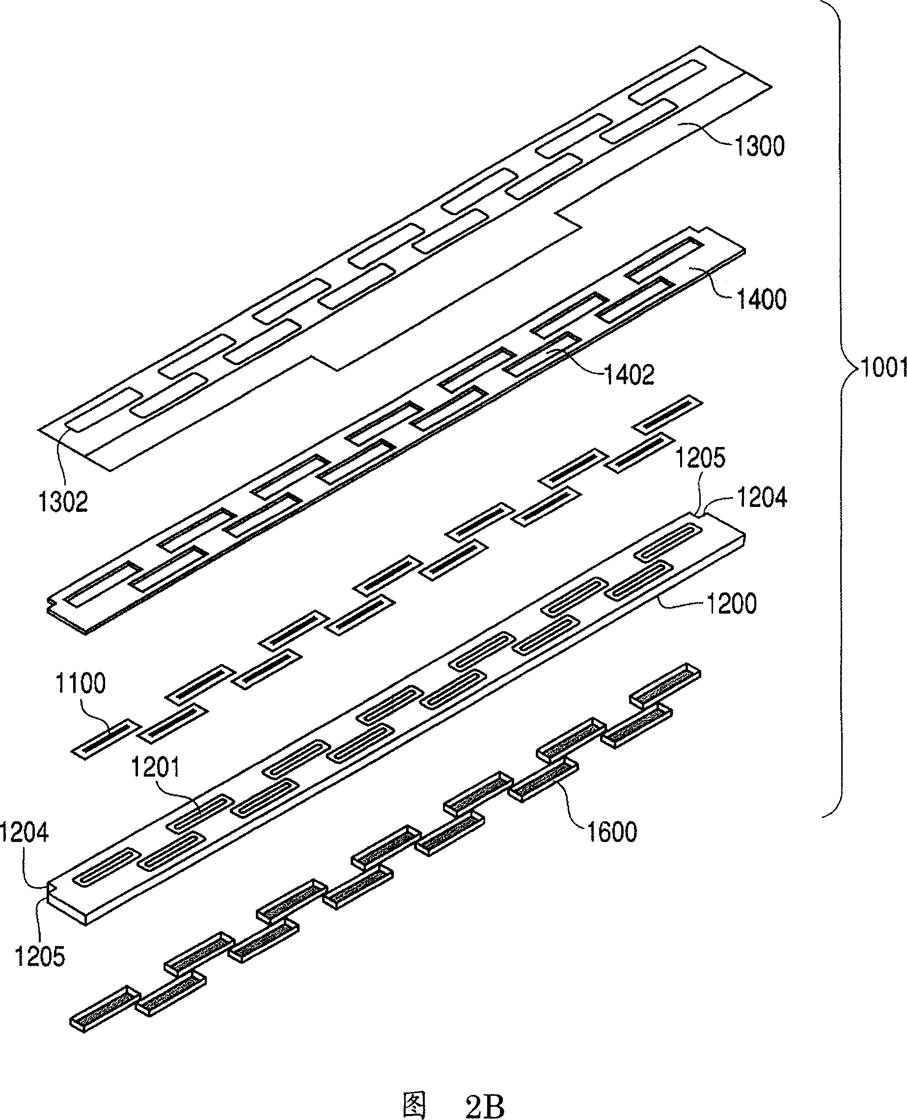
[0061] A first embodiment of the present invention will be described with reference to FIGS. 1 to 21B.
[0062] As shown in FIG. 1 , the main body of a recording device 4000 (hereinafter referred to as recording device main body 4000 for brevity) as a liquid discharge device according to an embodiment of the present invention is equipped with, for example, 6-color cameras corresponding to the quality of recorded photographic images. record header. The recording head 1000BK is a recording head for black ink, the recording head 1000C is a recording head for cyan ink, the recording head 1000M is a recording head for magenta ink, the recording head 1000Y is a recording head for yellow ink, and the recording head 1000LC is a light ink. As a recording head for cyan ink, the recording head 1000LM is a recording head for light magenta ink. It should be noted that, hereinafter, the recording heads 1000BK, 1000C, 1000M, 1000Y, 1000LC, and 1000LM may only be collectively referred to as ...
Embodiment 2
[0105] Next, a second embodiment related to the present invention will be described with reference to FIGS. 22A to 29B.
[0106] 22A is a perspective view showing one recording element substrate 1100 of the recording head 1000 and its enlarged periphery, and FIG. 22B is a cross-sectional view taken along line 22B-22B of FIG. 22A . Here, it should be noted that FIGS. 28A and 28B , and FIGS. 29A and 29B also each consist of a perspective view and a cross-sectional view.
[0107] Incidentally, although a method using wire bonding, a method using inner wire bonding (ILB), a method using anisotropic conductive film (ACF), etc. are used in practice as specific electrical connection methods, it should be noted that this Examples apply to any method.
[0108] The electrode 1103 and the electric wiring substrate 1300 through which the recording element substrate 1300 is connected to each other are connected by a bonding wire 1111 formed by a wire bonding method, thereby establishing a...
Embodiment 3
[0148] A third embodiment of the present invention will be described below with reference to FIGS. 30A to 43B.
[0149] 30A is a perspective view showing the recording element substrate 1100 of the recording head 1000 and its enlarged periphery, and FIG. 30B is a cross-sectional view taken along line 30B-30B of FIG. 30A . Here, it should be noted that FIGS. 31A to 43B are also similarly composed of perspective views and cross-sectional views.
[0150] Incidentally, although a method using wire bonding, a method using inner wire bonding (ILB), a method using anisotropic conductive film (ACF), etc. are practically employed as specific electrical connection methods, it should be noted that this Embodiments are applicable to any method. Incidentally, when the wire bonding method is performed, the extended portion of the protective film 2100 of the electrical wiring substrate 1300 is folded back and temporarily fixed at a position away from the electrical connection portion so tha...
PUM
 Abstract
Description
Claims
Application Information
 - R&D
- Intellectual Property
- Life Sciences
- Materials
- Tech Scout
- Unparalleled Data Quality
- Higher Quality Content
- 60% Fewer Hallucinations
Browse by: Latest US Patents, China's latest patents, Technical Efficacy Thesaurus, Application Domain, Technology Topic, Popular Technical Reports.
© 2025 PatSnap. All rights reserved.Legal|Privacy policy|Modern Slavery Act Transparency Statement|Sitemap|About US| Contact US: help@patsnap.com


