Mould for forming mold-shell structural component

A mold shell component, forming mold technology, applied in the direction of molds, ceramic molding machines, manufacturing tools, etc., can solve the problems of poor product quality, waste of materials, non-compliance with product quality requirements, etc.

Inactive Publication Date: 2007-06-20
邱则有
View PDF0 Cites 3 Cited by
  • Summary
  • Abstract
  • Description
  • Claims
  • Application Information

AI Technical Summary

Problems solved by technology

In the production process, the frame mold is placed on the working surface, the slurry is placed in the frame mold, and the slurry is scraped and smoothed manually with a scraper, and the production is completed after it is solidified and hardened. For production, the labor intensity is high, the production efficiency is low, all are manual operations, the thickness and strength of each part of the component are uneven, and the product quality is poor. Moreover, the production of component parts of different sizes requires molds of different sizes, which is easy to cause mold materials. waste, and when the working surface where the mold is placed is uneven, the slurry is easy to flow out from the gap between the mold and the working surface, forming a protruding edge, making the parts of the module irregular and not meeting the product quality requirements, increasing the Defective or scrap rate, waste of materials, and, can not achieve mechanized automatic production

Method used


Image

  • Mould for forming mold-shell structural component
  • Mould for forming mold-shell structural component
  • Mould for forming mold-shell structural component

Examples


Embodiment Construction

[0047] The present invention will be further described below in conjunction with the accompanying drawings and embodiments.

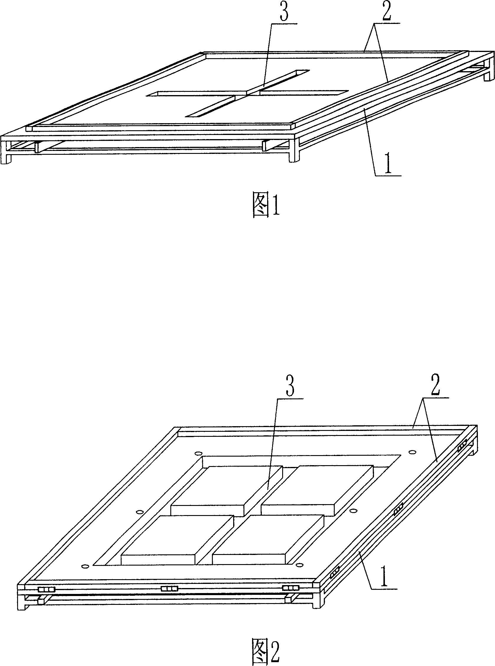
[0048] As shown in the accompanying drawings, the present invention includes a bottom template 1 and an outer frame 2, and is characterized in that the bottom template 1 is provided with a downwardly recessed groove 3. In each accompanying drawing, 1 is a plate, and 2 is a reinforcing rib. In the following accompanying drawings, those with the same number have the same description. As shown in FIG. 1 , the component forming mold of the formwork member includes a bottom template 1 and an outer frame 2 , and it is characterized in that the bottom template 1 is provided with a downwardly recessed groove 3 .

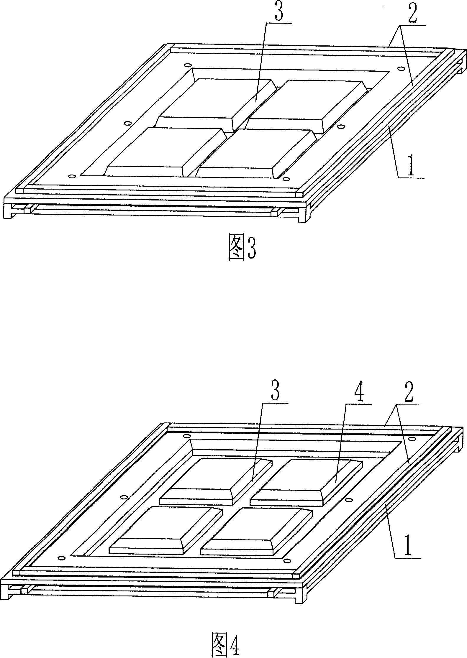
[0049] The present invention is also characterized in that the groove 3 is one, two or more strip-shaped grooves. As shown in FIG. 2 , the groove 3 is a plurality of strip grooves.

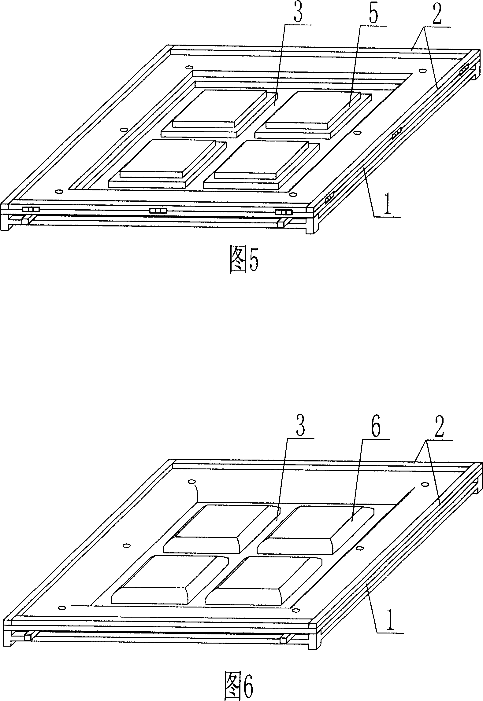
[0050] The present invention is also characterized in that the groov...


PUM


Abstract

A mould for forming the part of molding shell member is composed of a bottom plate with slots and an external frame. Said slots on bottom plate can result in the convex reinforcing ribs on plate product.

Description

(1) Technical field [0001] The present invention relates to a component molding die for a formwork member. (2) Background technology [0002] At present, the production of formwork components used for filling the cast-in-place concrete hollow floor in China usually adopts manual operation, and the molds used are generally made of wooden squares or steel bars to form frame molds. In the production process, the frame mold is placed on the working surface, the slurry is placed in the frame mold, and the slurry is scraped and smoothed manually with a scraper, and the production is completed after it is solidified and hardened. For production, the labor intensity is high, the production efficiency is low, all are manual operations, the thickness and strength of each part of the component are uneven, and the product quality is poor. Moreover, the production of component parts of different sizes requires molds of different sizes, which is easy to cause mold materials. waste, and w...

Claims


Application Information

Patent Timeline
Patent Type & Authority Applications(China)
IPC IPC(8): B28B7/22B28B1/29
Inventor 邱则有
Owner 邱则有
Why Eureka
Try Eureka