
A multi-carrier communication system

A multi-carrier communication and multi-carrier signal technology, which is applied in the field of communication systems, can solve the problems of no explanation, gain adjustment, etc., and achieve the effects of convenient implementation, improved efficiency, and good clipping effect

Inactive Publication Date: 2010-12-08
ZTE CORP
View PDF7 Cites 0 Cited by
  • Summary
  • Abstract
  • Description
  • Claims
  • Application Information

AI Technical Summary

Problems solved by technology

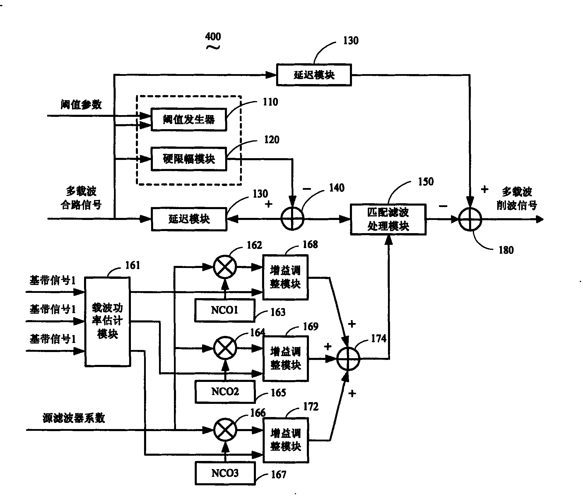
Unfortunately, the technical invention patent does not specify how to adjust the gain of each carrier matched filter coefficient, and how to adjust each carrier matched filter coefficient in real time, especially how to adjust each matched filter in system implementation gain

Method used


Image

  • A multi-carrier communication system
  • A multi-carrier communication system
  • A multi-carrier communication system

Examples


Embodiment Construction

[0020] The present invention can be fully explained and understood by the detailed description provided below in conjunction with the accompanying drawings, and the features, properties and advantages of the present invention will become more apparent.

[0021] In the wireless transmitter of the wireless communication system, the clipping technique is used to reduce the peak-to-average ratio of multi-carrier signals entering the power amplifier, so as to improve the efficiency of the power amplifier and reduce the cost of the power amplifier.

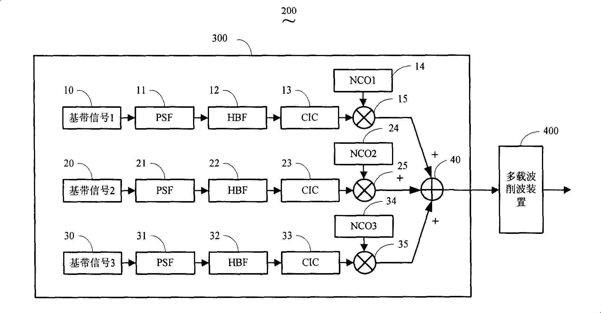
[0022] Please refer to figure 1 . This figure is a schematic diagram of the location of the multi-carrier signal generating device 300 and the multi-carrier clipping device 400 in the present invention. A multi-carrier signal is formed by superimposing multiple single-carrier signals. For each single-carrier signal, its generation process is the same, so only the generation process of one of the single-carrier signals is used for illus...


PUM


Abstract

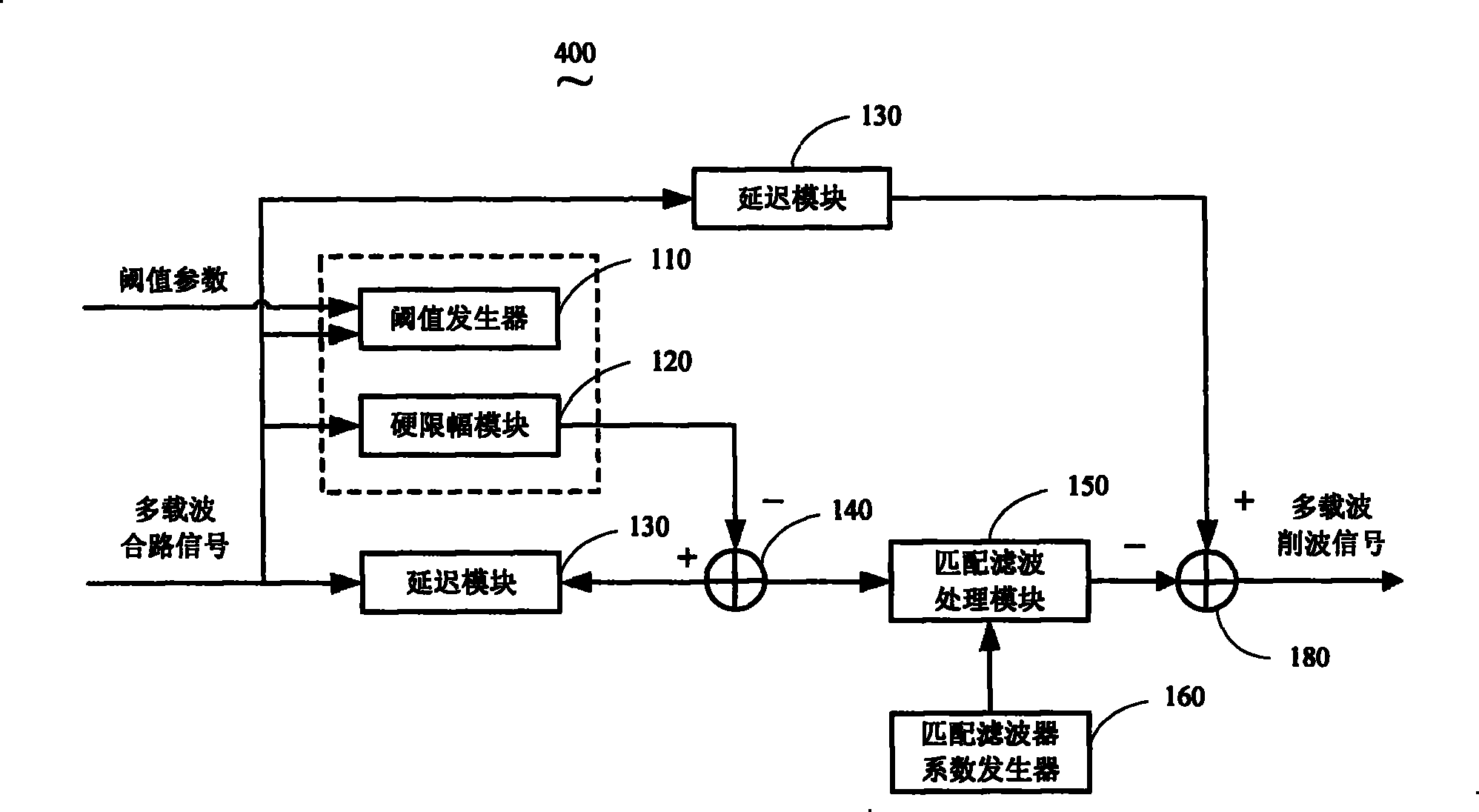
This invention relates to multi-load communication system, which comprises one multi-load wave signals generation device and one multi-load peak remove device, wherein, the peak remove device is to reduce peak proportion of the multi-load signals generated by the device; the multi-load signals generation device comprises several single load wave signal generation module and sum module; the said remove device comprises hard limit range device, sum device, match filter parameter generation device and match filter process device.

Description

【Technical field】 [0001] The invention relates to a communication system, in particular to a multi-carrier communication system which reduces the peak-to-average ratio of signals entering a power amplifier. 【Background technique】 [0002] As we all know, a transmitter of a wireless base station in a mobile communication system uses a power amplifier to transmit signals to compensate for signal attenuation caused by propagation distance. The power amplifier has a certain linear region, and the cost of the power amplifier is determined by the size of its linear region. A signal with a peak-to-average ratio will reduce the efficiency of the power amplifier and increase power consumption, which puts high demands on the linearity of the power amplifier. In order to ensure that the power amplifier works in the linear region to improve its efficiency, the peak-to-average ratio of the signal entering the power amplifier is required to be below a certain range. [0003] In mobile c...

Claims


Application Information

Patent Timeline
Patent Type & Authority Patents(China)
IPC IPC(8): H04L27/26
Inventor 游爱民
Owner ZTE CORP
Learn More