Method of squeezing foundry sand, match plate, and upper and lower flasks
一种双面模板、压板的技术,应用在型箱、造型机、造型台等方向,能够解决硬度和强度不够充分等问题
- Summary
- Abstract
- Description
- Claims
- Application Information
AI Technical Summary
Problems solved by technology
Method used
Image

Examples
Embodiment 1
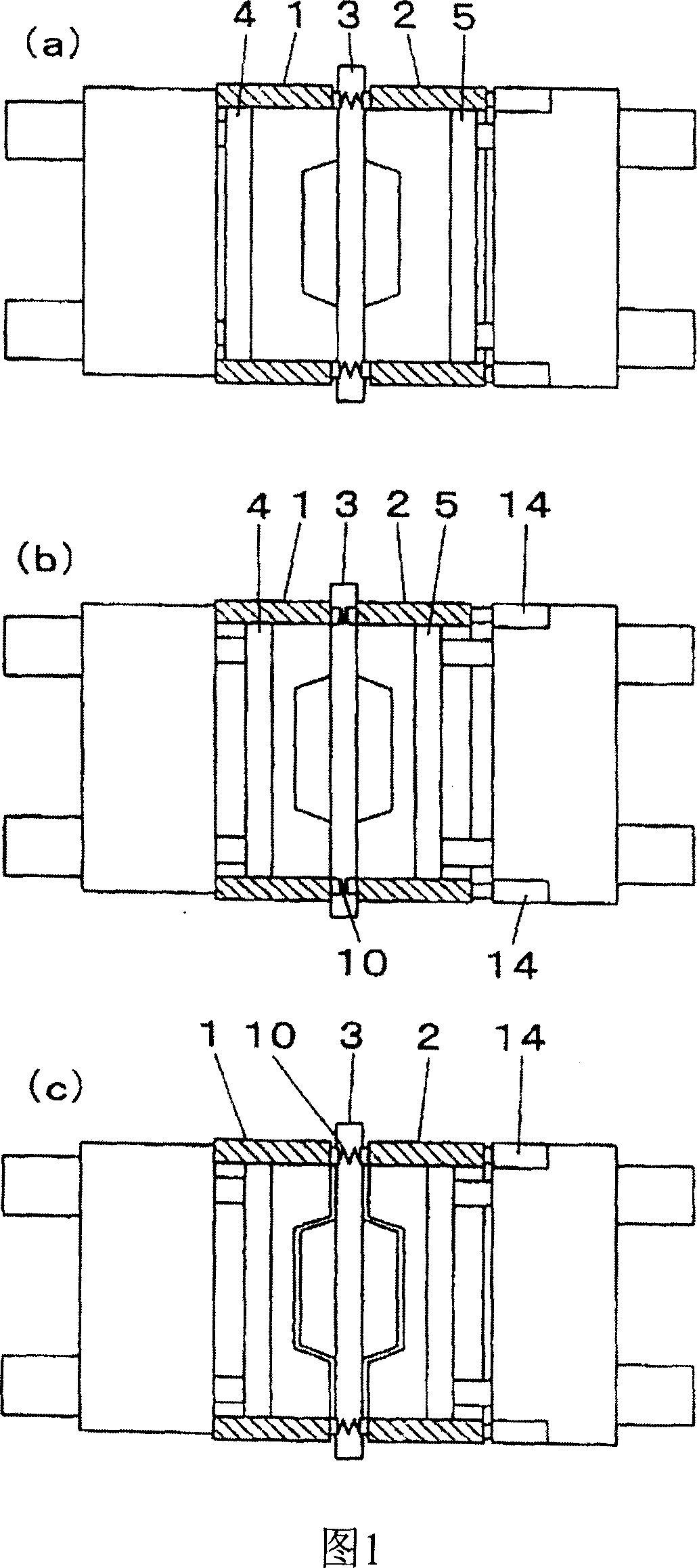
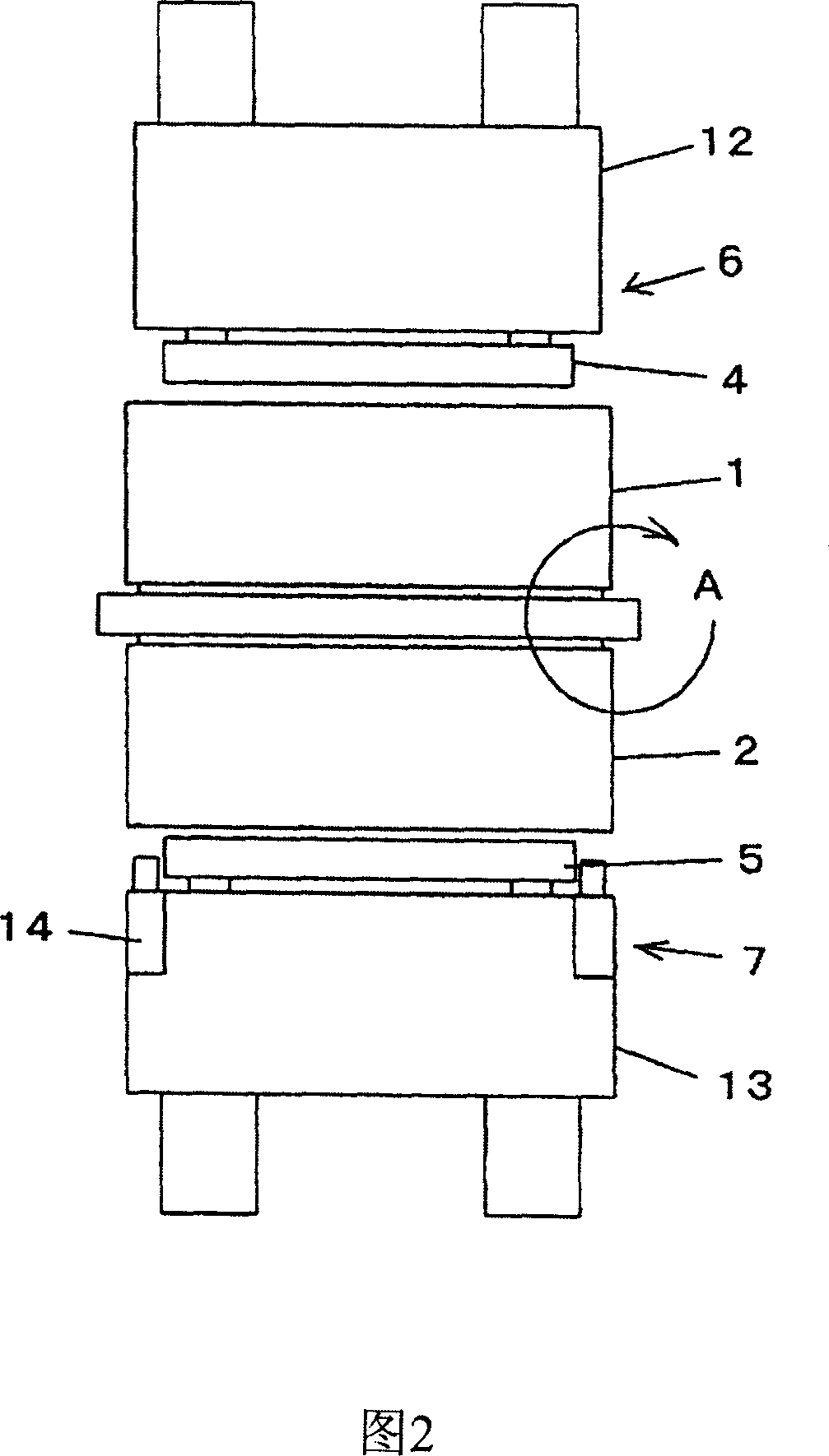
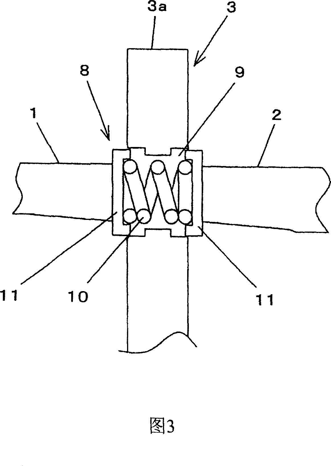
[0032] An embodiment of the molding sand compression method and the double-sided formwork used in the present invention will be described in detail with reference to FIGS. 1-4 .
[0033] As shown in Figures 2-4, the above-mentioned double-sided formwork 3 is provided with a double-sided formwork 3 that can pass through the above-mentioned upper and lower sand boxes 1, 2 at the perimeter edge position of the model part of its double-sided formwork body 3a. The push of the side end face shrinks the telescopic device 8 . As shown in Figure 3, the telescopic device 8 includes a plurality of compression coil springs 10, 10 that are respectively arranged on the inside of the plurality of through holes 9 formed on the above-mentioned double-sided template body 3a, and are mounted on the above-mentioned double-sided template body 3a The upper compression coil springs 10, 10 compress the clamped box-shaped support members 11, 11 left and right. And as shown in Figure 4, the plurality ...
Embodiment 2
[0036] Embodiments using other retractable devices will be described in detail with reference to FIGS. 5-7 . As shown in Fig. 5-Fig. 7, on the edge position of the perimeter of double-sided formwork 21 model part, be provided with and can shrink through the pushing of the side end faces adjacent to double-sided formwork 21 of above-mentioned upper and lower sand box 1,2. The retractable device 20. The telescopic device 20, as shown in Figure 6, includes a plurality of compression coil springs 23, 23 disposed in a plurality of through holes 22, 22 formed on the above-mentioned double-sided template 21, and the plurality of compression coil springs 23 , 23 are clamped from the up and down direction and the cross-sectional shape is a box-shaped support member 24, 24 of U shape. And as shown in Figure 7, the plurality of compression coil springs 23,23 that are arranged on the above-mentioned telescopic device 20 can be arranged on the perimeter of the model part at equal interval...
Embodiment 3
[0039]Embodiments using other retractable devices will be described in detail below with reference to FIGS. 8-10 . As shown in Figures 8-10, the end faces of the above-mentioned upper and lower sand boxes 30, 31 and the side adjacent to the above-mentioned double-sided formwork 21 are provided with the end faces of the above-mentioned upper and lower sand boxes 30, 31 and the double-sided formwork 21. Squeeze and shrink the first telescopic device 32, as shown in Figure 9, the first telescopic device 32 includes pins 33, 33 that protrude from the inside of the upper and lower sand boxes 30, 31 and can slide freely, and are arranged on Compression coil springs 34 , 34 inside the upper and lower flasks 30 , 31 apply pressure in the direction in which the pins 33 , 33 extend. The end surfaces of the above-mentioned pins 33 and 33 face the end surfaces of the double-sided template 21 and are in contact with it. As shown in FIG. 10 , the pins 33 and 33 provided on the first telesc...
PUM
 Abstract
Description
Claims
Application Information
 - R&D
- Intellectual Property
- Life Sciences
- Materials
- Tech Scout
- Unparalleled Data Quality
- Higher Quality Content
- 60% Fewer Hallucinations
Browse by: Latest US Patents, China's latest patents, Technical Efficacy Thesaurus, Application Domain, Technology Topic, Popular Technical Reports.
© 2025 PatSnap. All rights reserved.Legal|Privacy policy|Modern Slavery Act Transparency Statement|Sitemap|About US| Contact US: help@patsnap.com