Switching-mode power supply
一种开关电源、开关的技术,应用在输出功率的转换装置、电气元件、高效电力电子转换等方向,能够解决不能正确且容易同步整流用开关最佳控制等问题
- Summary
- Abstract
- Description
- Claims
- Application Information
AI Technical Summary
Problems solved by technology
Method used
Image

Examples
Embodiment 1
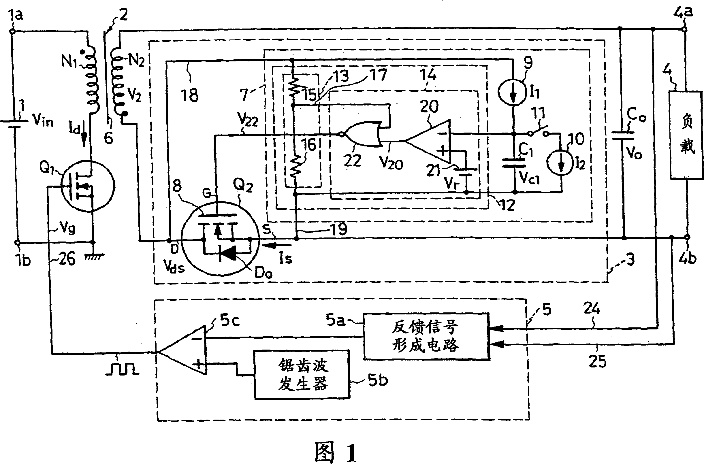
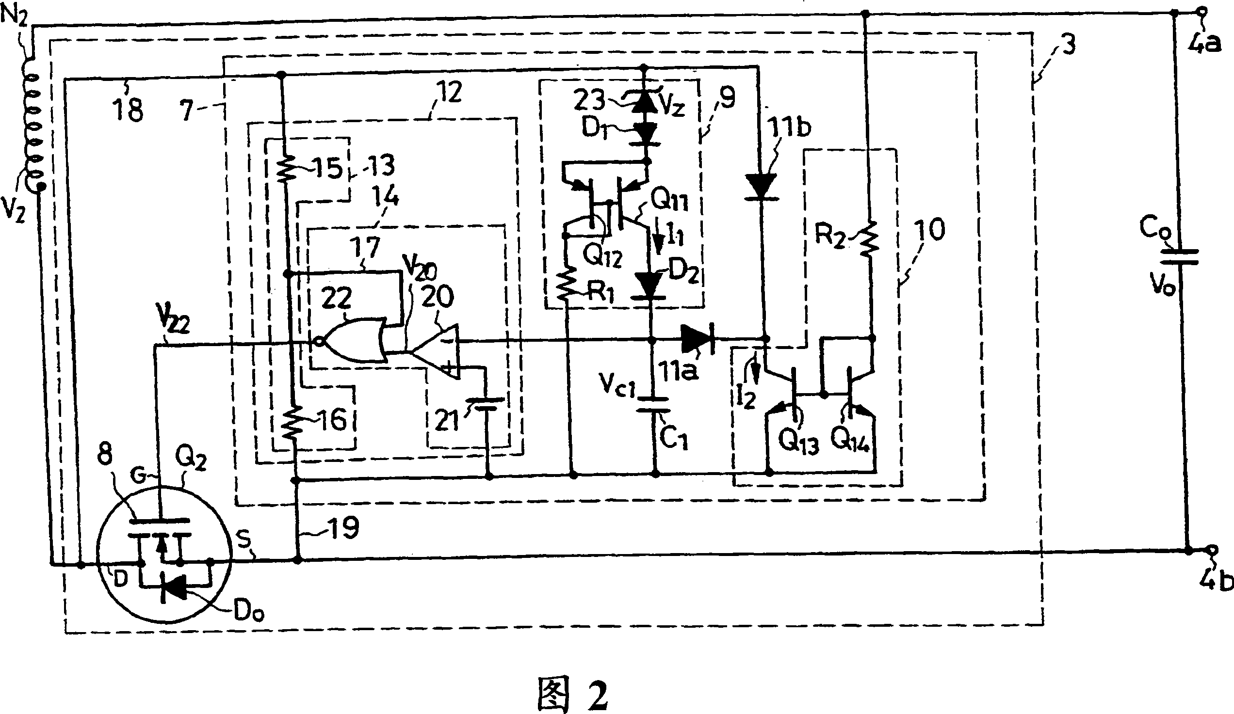
[0013] The switching power supply device constituted by the flyback type DC-DC converter of Embodiment 1 of the present invention shown in FIG. 1 includes: a pair of DC power supply terminals 1a, 1b as a DC voltage input unit connected to the DC power supply 1; A transformer 2 as an inductance unit; a main switch Q1 as an intermittent voltage supply unit; a synchronous rectification circuit 3; a smoothing capacitor Co; a pair of DC output terminals 4a, 4b connected to a load 4;
[0014] The DC power supply 1 is composed of a rectifying and smoothing circuit connected to a commercial AC power supply, a battery, etc., and supplies a DC input voltage Vin to a pair of DC power supply terminals 1a, 1b.
[0015] The transformer 2 as an inductance unit is composed of a primary winding N1 and a secondary winding N2 that are respectively wound around a magnetic core 6 and are electromagnetically coupled to each other. In this embodiment, as indicated by black dots, the primary winding ...
Embodiment 2
[0044] Next, a switching power supply device will be described based on Embodiment 2 shown in FIG. 4 . However, in FIG. 4 and FIGS. 5 to 16 described later, parts substantially the same as those in FIGS. 1 and 2 are denoted by the same symbols, and description thereof will be omitted. 1 and 3 are referred to in the description of FIGS. 4 to 16 .
[0045] The switching current device in FIG. 4 is formed in the same manner as in FIGS. 1 and 2 except that it has a modified synchronous rectification circuit 3a. In addition, the modified synchronous rectification circuit 3 a of FIG. 4 is formed in the same manner as that of FIG. 2 except for the modified synchronous rectification control circuit 7 a.
[0046] The synchronous rectification control circuit 7a of FIG. 4 is formed in the same manner as that of FIG. 2 except for the modified first current source 9a. The first collector resistor in the first current source 9a in FIG. 4 is connected between the collector of the second t...
Embodiment 3
[0048] The switching power supply device of the third embodiment shown in FIG. 5 has the same configuration as that of FIG. 1, FIG. 2 and FIG. 4 except for the modified synchronous rectification circuit 3b. In addition, the synchronous rectification circuit 3b of FIG. 5 is formed similarly to FIG. 4 except for the modified synchronous rectification control circuit 7b.
[0049] The synchronous rectification control circuit 7b of FIG. 5 omits the selective discharge diode 11a and the bias diode 11b of FIG. 4, and instead sets two voltage dividing resistors 31, 32, a comparator 33, and a reference voltage source 34 as discharge prohibition units. And the switch Q5 for discharge control is formed similarly to FIG. 4 except for this.
[0050] The third transistor Q13 in FIG. 5 is directly connected in parallel with the capacitor C1. A discharge control switch Q5 composed of FETs for turning on the third and fourth transistors Q13 and Q14 only during the OFF period of the main swit...
PUM
 Abstract
Description
Claims
Application Information
 - R&D
- Intellectual Property
- Life Sciences
- Materials
- Tech Scout
- Unparalleled Data Quality
- Higher Quality Content
- 60% Fewer Hallucinations
Browse by: Latest US Patents, China's latest patents, Technical Efficacy Thesaurus, Application Domain, Technology Topic, Popular Technical Reports.
© 2025 PatSnap. All rights reserved.Legal|Privacy policy|Modern Slavery Act Transparency Statement|Sitemap|About US| Contact US: help@patsnap.com