Bi service electromagnetic valve
A solenoid valve, dual-purpose technology, applied in the field of solenoid valves, can solve problems such as inconvenience, and achieve the effects of reducing processing requirements, simplifying structure, and improving sealing performance
- Summary
- Abstract
- Description
- Claims
- Application Information
AI Technical Summary
Problems solved by technology
Method used
Image

Examples
Embodiment 1
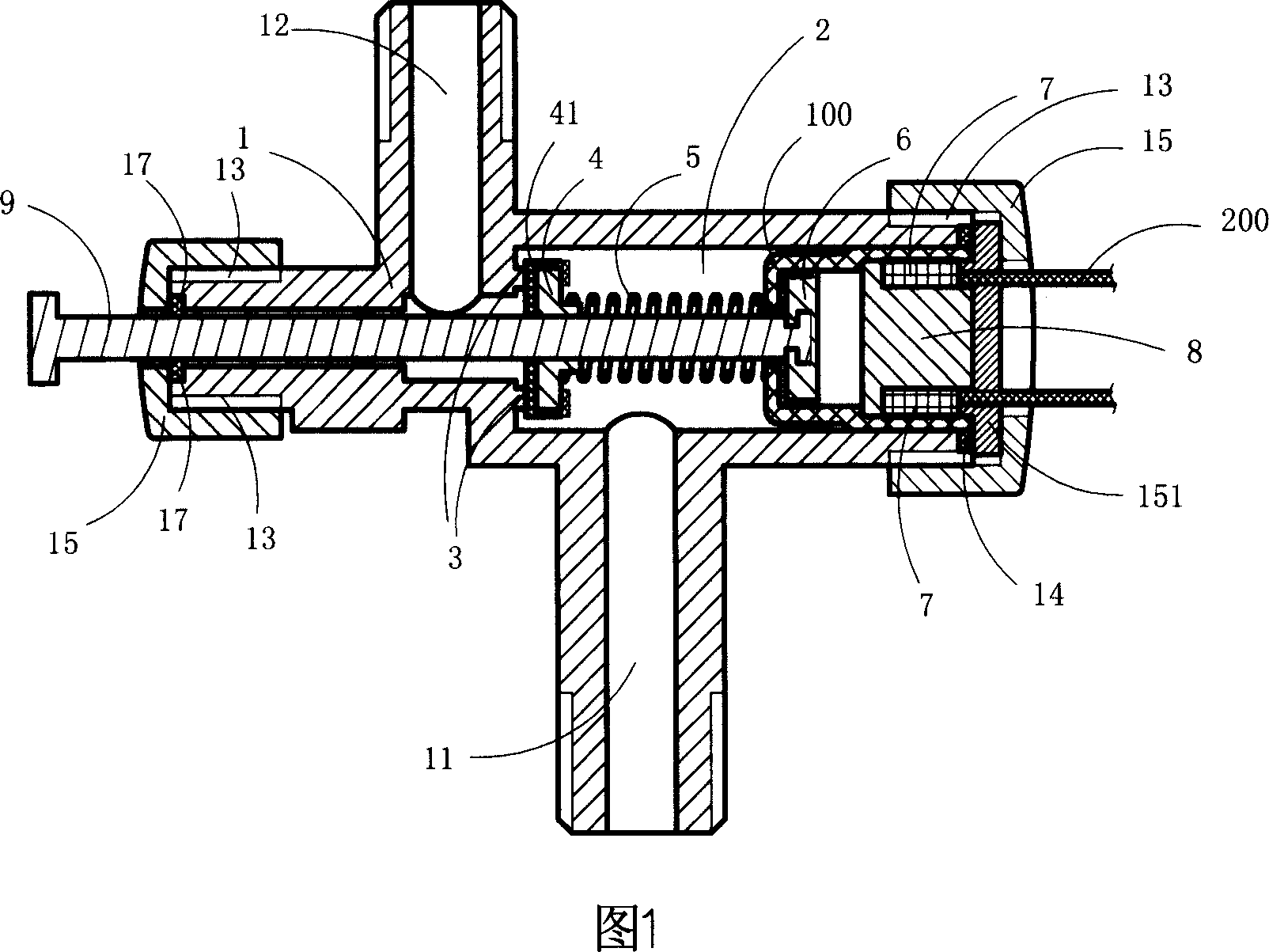
[0022] As shown in Figure 1, this embodiment is a dual-purpose solenoid valve that can be opened manually or electrically. It has a valve body 1, a valve cavity 2 surrounded by the valve body 1, an inlet channel 11 and an outlet channel 12 , the valve seat 3, the valve core 4, the spring 5, the moving iron core 6, the winding 7, the static iron core 8, and the push rod 9 are arranged in the valve chamber 2; the valve chamber 2, the inlet channel 11 and the outlet channel 12 communicate with each other, The spring 5 is located between the valve core 4 and the static iron core 8 and sleeved on the push rod 9, the winding 7 is arranged around the static iron core 8; one end of the push rod 9 protrudes The valve cavity 2 is exposed outside the valve cavity 2 , and the other end of the push rod 9 extends into the valve cavity 2 and is fixedly connected with the moving iron core 6 .
[0023] The number of the winding 7 is one, and it is arranged in the valve chamber 2 around the sta...
Embodiment 2
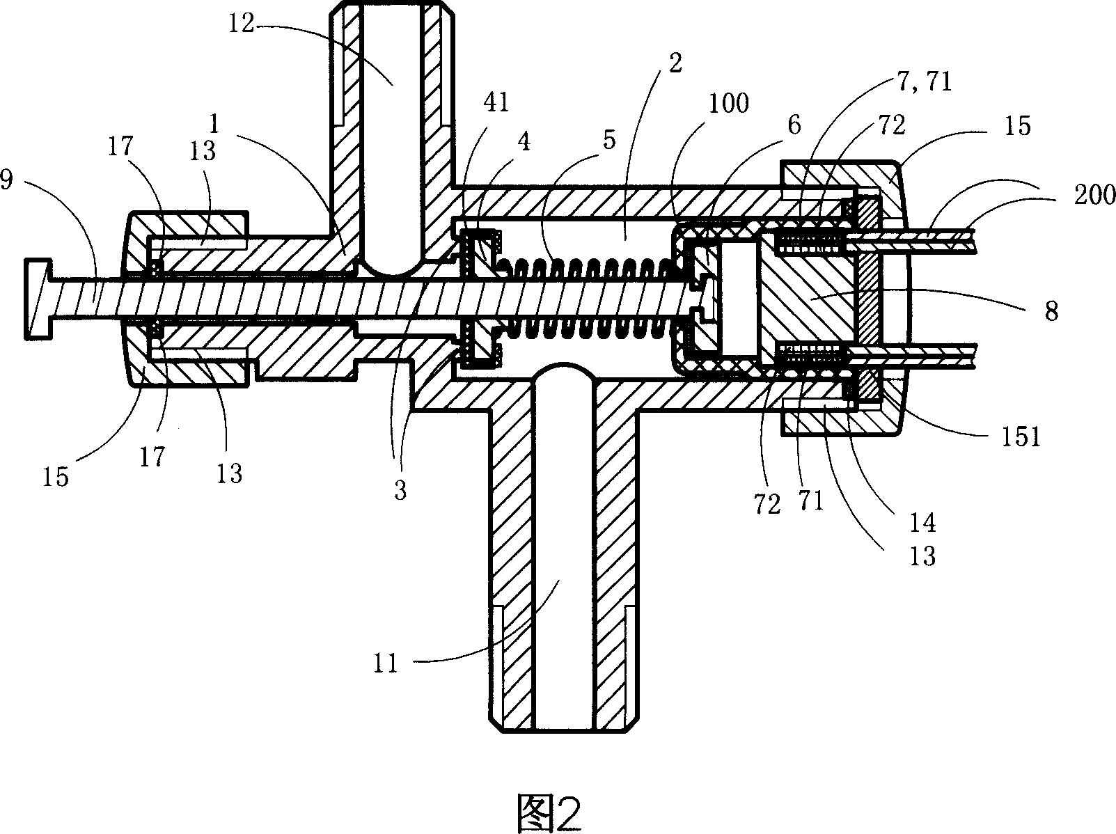
[0030] As shown in Fig. 2, this embodiment is basically the same as Embodiment 1, except that the dual-purpose solenoid valve of this embodiment has two windings 7 arranged in the valve chamber 2 around the static iron core 8, which are respectively the outer windings 71 and inner winding 72. The two windings can be connected to the lower voltage power supply and the higher voltage power supply respectively, so that under the action of the higher voltage power supply of the present invention, one of the windings can provide greater adsorption force to realize automatic electric start. It can also make the other winding provide a small adsorption force under the action of a lower voltage power supply after it is turned on, so as to maintain the normally on state. The winding 7 in this embodiment is connected to an external power source through four wires 200 .
[0031] Compared with the dual-purpose solenoid valve in Embodiment 1, the dual-purpose solenoid valve in this embodi...
Embodiment 3
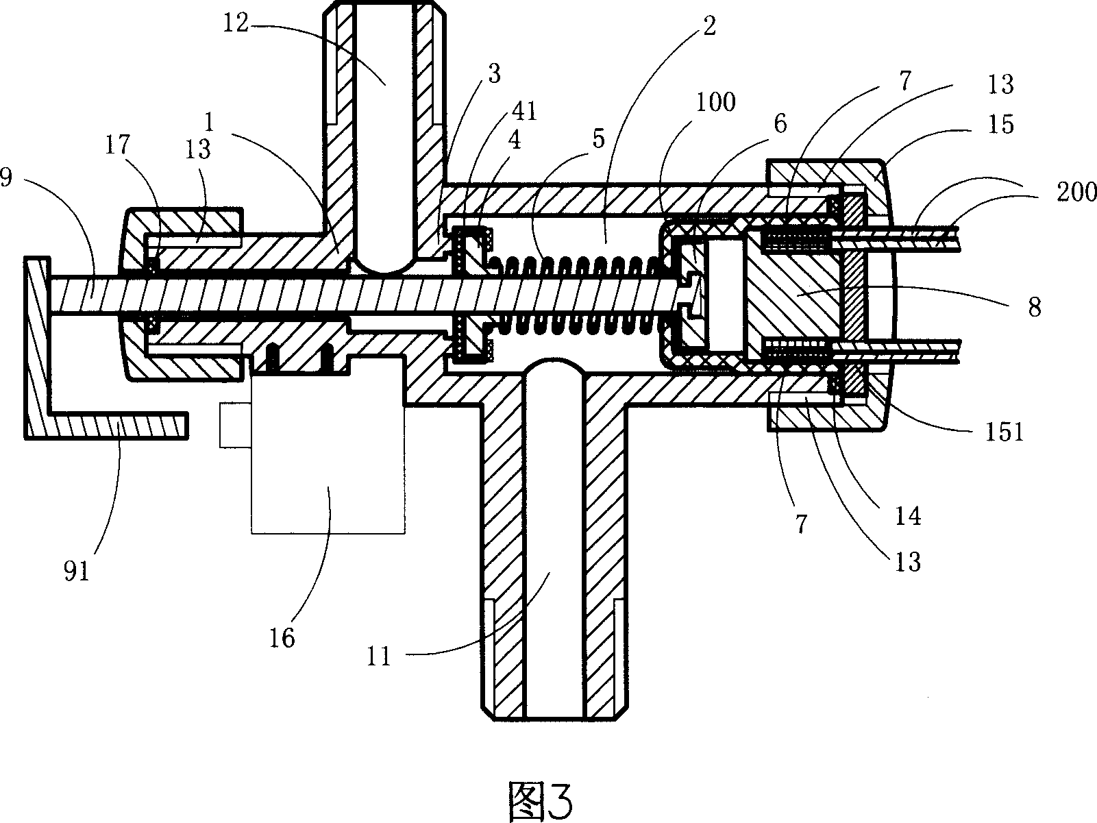
[0033] As shown in Fig. 3, this embodiment is basically the same as Embodiment 2, the difference is that: the valve body 1 of this embodiment is also fixed with a micro switch 16, and the part of the push rod 9 exposed outside the valve cavity 2 A triggering part 91 is fixedly arranged on the top, and the triggering part 91 can move along with the movement of the push rod 3 and trigger the micro switch 16 .
[0034] When the dual-purpose solenoid valve of this embodiment is in use, the microswitch 16 can be electrically connected to the winding 7, that is, the microswitch 16 is used to control whether the winding 7 is energized, so that when the push rod 9 is pressed, The triggering component 91 is driven to trigger the microswitch 16, so that the winding 7 is energized at the same time, so as to generate an adsorption force to maintain the conduction state of the dual-purpose solenoid valve of this embodiment.
PUM
 Abstract
Description
Claims
Application Information
 - R&D
- Intellectual Property
- Life Sciences
- Materials
- Tech Scout
- Unparalleled Data Quality
- Higher Quality Content
- 60% Fewer Hallucinations
Browse by: Latest US Patents, China's latest patents, Technical Efficacy Thesaurus, Application Domain, Technology Topic, Popular Technical Reports.
© 2025 PatSnap. All rights reserved.Legal|Privacy policy|Modern Slavery Act Transparency Statement|Sitemap|About US| Contact US: help@patsnap.com