
Hermetic two-stage rotary compressor

A technology of rotary compressors and compressors, which is applied in the direction of rotary piston machinery, mechanical equipment, machines/engines, etc., can solve the problems of complex structure and cost increase, and achieve the effect of simple structure and cost reduction

Inactive Publication Date: 2007-05-09
HITACHI APPLIANCES INC
View PDF2 Cites 27 Cited by
  • Summary
  • Abstract
  • Description
  • Claims
  • Application Information

AI Technical Summary

Problems solved by technology

[0007] However, in the hermetic two-stage rotary compressor of Patent Document 2, since the planar arrangement angles of the low-stage compressor section and the high-stage compressor section are staggered, it is necessary to adjust the low-stage compressor section and the high-stage compressor section. However, setting the connecting screw hole pitches for connecting the low-stage compressor part and the high-stage compressor part separately made the structure complicated and led to a problem of cost increase.

Method used


Image

  • Hermetic two-stage rotary compressor
  • Hermetic two-stage rotary compressor
  • Hermetic two-stage rotary compressor

Examples


no. 1 Embodiment approach

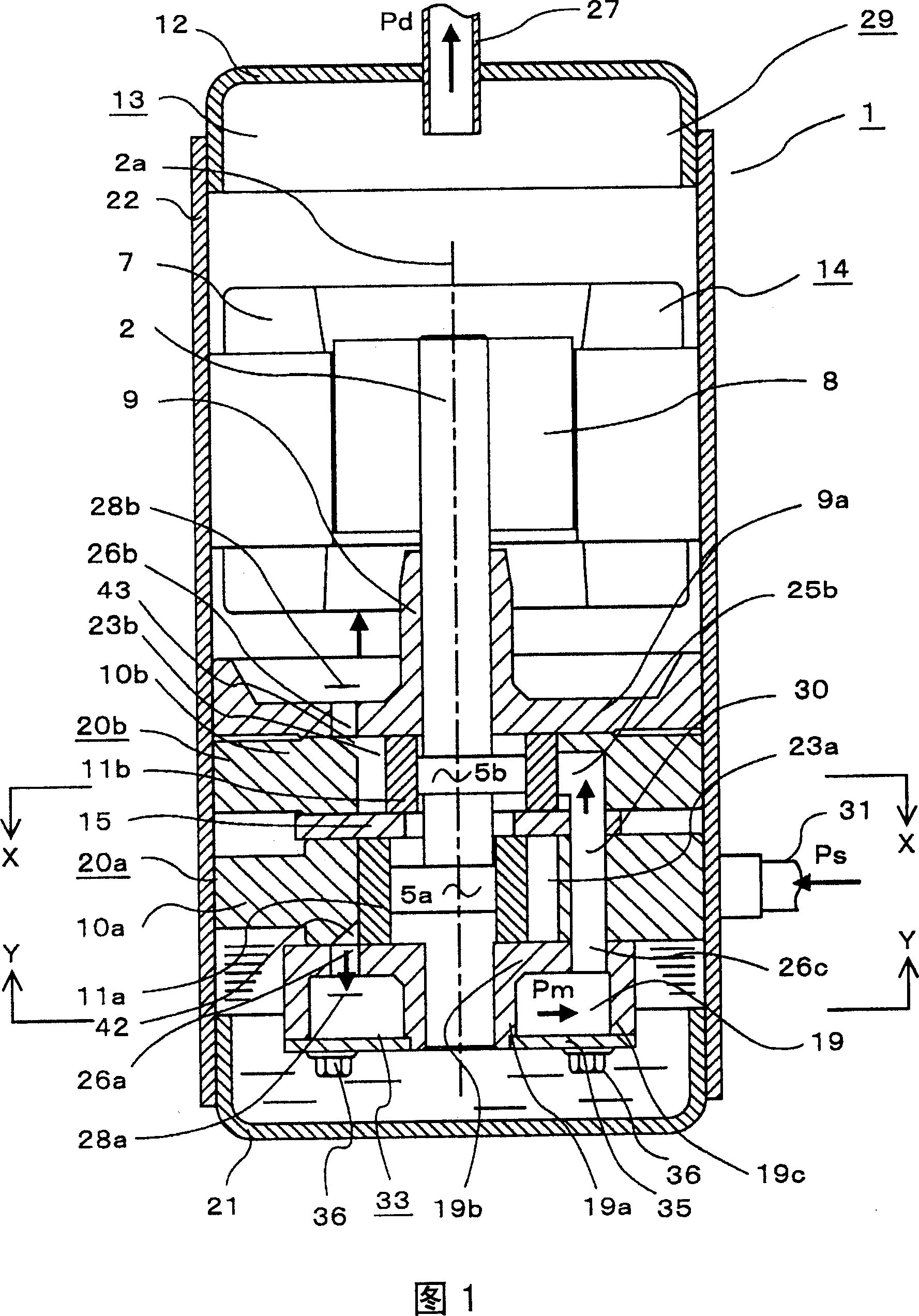
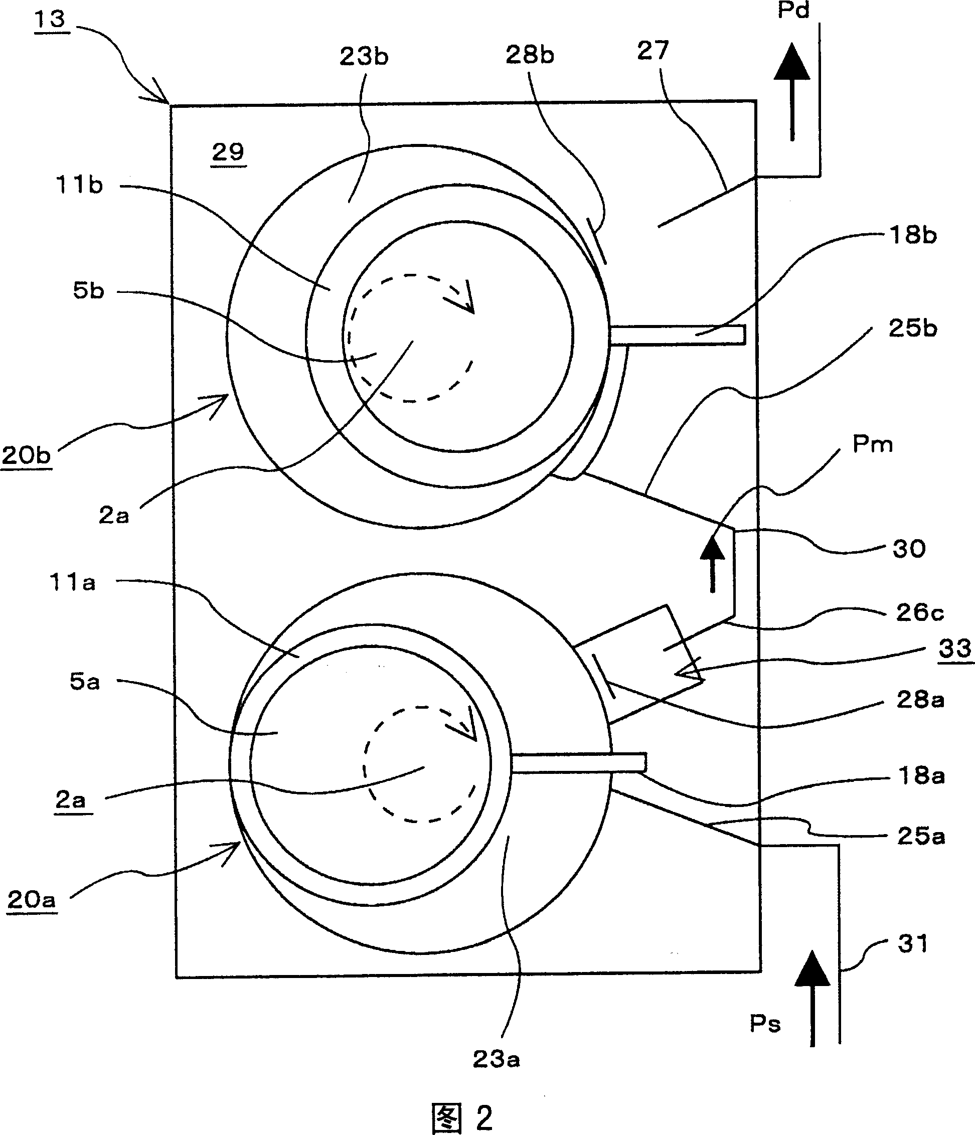
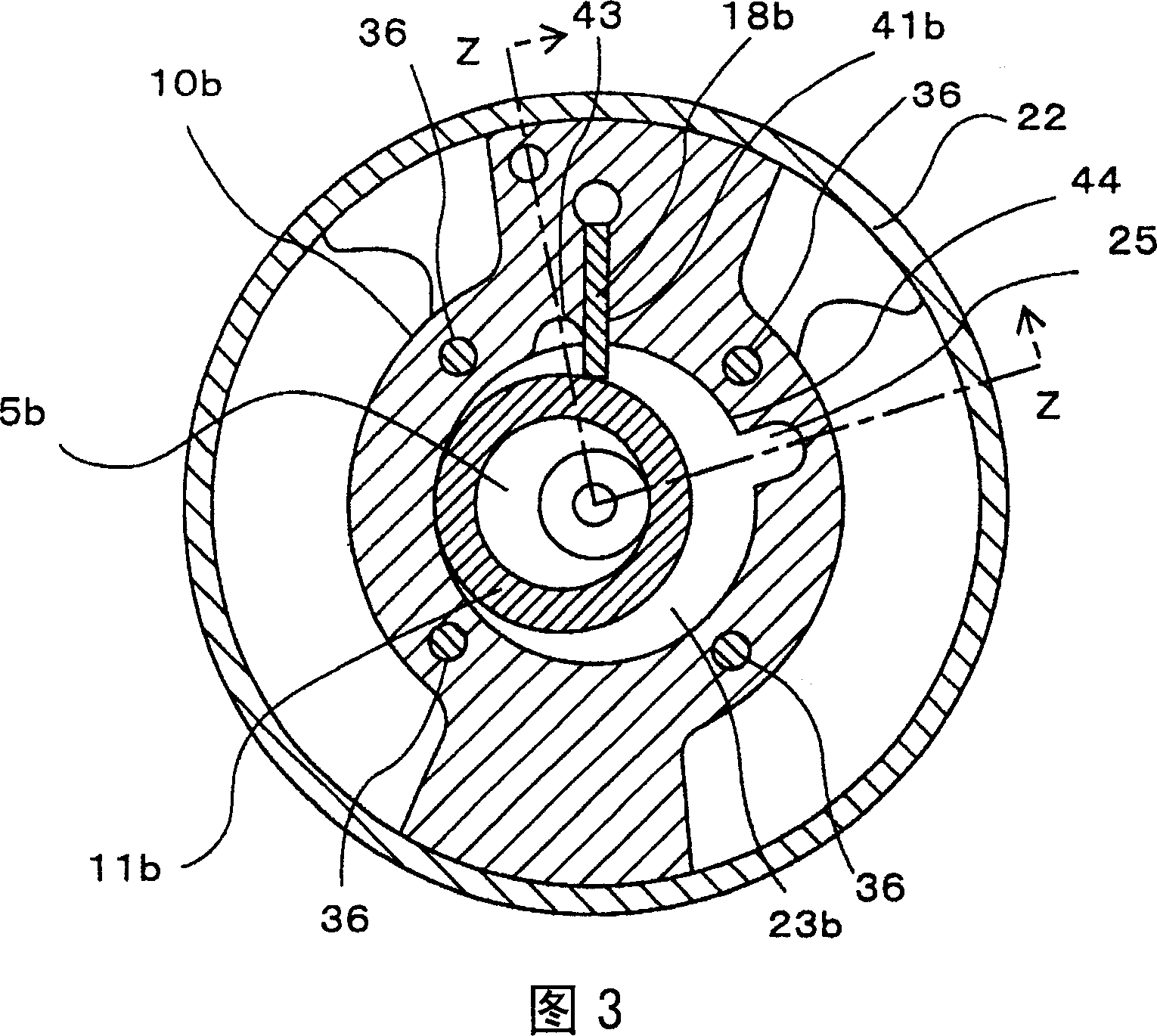
[0032] A hermetic two-stage rotary compressor according to a first embodiment of the present invention will be described with reference to FIGS. 1 to 4 . Fig. 1 is a longitudinal sectional view of a hermetic two-stage rotary compressor according to a first embodiment, and Fig. 2 is a schematic diagram showing a planar arrangement of a low stage compressor part and a high stage compressor part of a compression mechanism part according to the first embodiment , Fig. 3 is the X-X sectional view of Fig. 1, and Fig. 4 is the Y-Y sectional view of Fig. 1 . In addition, FIG. 1 is a Z-Z sectional view of FIG. 3 .

[0033] As shown in FIG. 1 , a hermetic two-stage rotary compressor 1 has a hermetic container 13 composed of a bottom 21 , a cover 12 , and a body 22 . An electric motor 14 having a stator 7 and a rotor 8 is provided in the upper part of the airtight container 13 . The outer periphery of the stator 7 is fixed to the airtight container 13 , and the rotor 8 is fixedly coupl...

no. 2 Embodiment approach

[0056] Next, a second embodiment of the present invention will be described with reference to FIGS. 5 to 7 . 5 is a longitudinal sectional view of a hermetic two-stage rotary compressor according to a second embodiment of the present invention, FIG. 6 is a X-X sectional view of FIG. 5 , and FIG. 7 is a Y-Y sectional view of FIG. 5 . In addition, FIG. 5 is a Z-Z sectional view of FIG. 6 .


PUM


Abstract

Disclosed is a hermetic two-stage rotary compressor in which a low stage compression element is connected with a high stage compression element with a simple structure to largely reduce a cost while shortening an intermediate communication passage. The hermetic two-stage rotary compressor 1 has the low stage compression element 20a and high stage compression element 20b driven by a crankshaft 2. The crankshaft has a low-stage eccentric part 5a, and a high-stage eccentric part 5b different in phase by 180 degrees from the low-stage eccentric part 5a. A low-stage end plate 19b, a low-stage cylinder 10a, a partition plate 15, a high-stage cylinder 10b, and a high-stage end plate 9a are integrally fastened through bolts 36, with a state where they are stacked in this order and plane angle positions of a vane groove of the low-stage cylinder and a vane groove of the high-stage cylinder are the same. An intermediate discharge space 33 in which gas of intermediate pressure is discharged communicates with a suction port 25 of a high-stage compression chamber 23b through the intermediate communication passage 30 passing through the low-stage end plate, low-stage cylinder, partition plate, and high-stage cylinder.

Description

technical field [0001] The present invention relates to a hermetic two-stage rotary compressor having a low-stage compressor part and a high-stage compressor part in a compression mechanism part, and particularly relates to a hermetic two-stage rotary compressor suitable for use in refrigerators such as air conditioners and air-conditioning products. Rotary compressor. Background technique [0002] As a hermetic two-stage rotary compressor, there is a compressor described in JP-A-63-138189 (Patent Document 1). In this hermetically sealed two-stage rotary compressor, the intermediate communication path is led out to the outside of the airtight container, and a buffer container is provided in the middle, and the volume of the intermediate communication path is set to be larger than the excluded volume of the compression chamber of the high-stage compressor, The intermediate communication path guides the gas discharged from the compression chamber of the low stage compressor p...

Claims


Application Information

Patent Timeline
Patent Type & Authority Applications(China)
IPC IPC(8): F04C23/00
CPCF04C18/356F04C23/001F04C23/008F04C2210/26F04C2240/40F16B5/02Y10S415/00Y10S417/00
Inventor 大沼敦田所哲也久保田淳关上和夫
Owner HITACHI APPLIANCES INC
Learn More