Refrigerant tank with volume below 1000ml

A refrigerant and tank body technology, applied in the field of refrigerant tank capping, can solve the problems of large refrigerant leakage, refrigerant moisture content reaching the standard, water content exceeding the standard, etc., saving resources, saving investment in production equipment, and eliminating the need for special The effect of the device

Inactive Publication Date: 2007-04-25
周飞
View PDF0 Cites 7 Cited by
  • Summary
  • Abstract
  • Description
  • Claims
  • Application Information

AI Technical Summary

Problems solved by technology

If there is no special equipment and technical means, it is difficult to ensure that the moisture content of the refrigerant in the small-package refrigerant tank reaches the standard, which is why most of the small-package refrigerants on the market contain water exceeding the standard.
The existing solution is to use more expensive under-cap filling equipment, but due to the high cost, many companies are reluctant to use it
Even if it is used, because this kind of equipment leaks a lot when filling the refrigerant, there is a problem of environmental pollution

Method used


Image

  • Refrigerant tank with volume below 1000ml
  • Refrigerant tank with volume below 1000ml
  • Refrigerant tank with volume below 1000ml

Examples


Embodiment 1

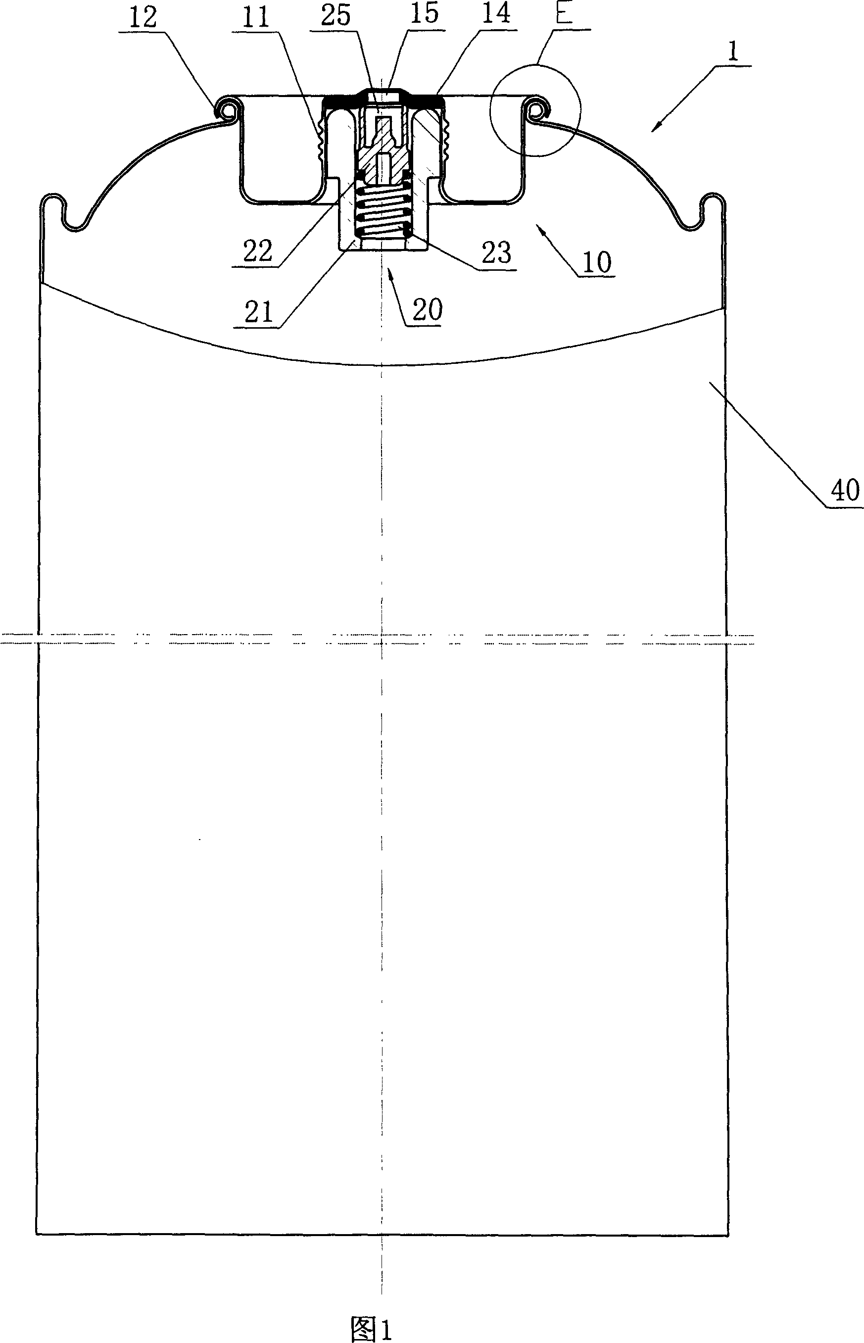
[0024] In this embodiment, a 600 milliliter refrigerant tank is used to fill 330 grams of hydrocarbon refrigerant. The steps are as follows:

[0025] a) Install the threaded aerosol valve for a while

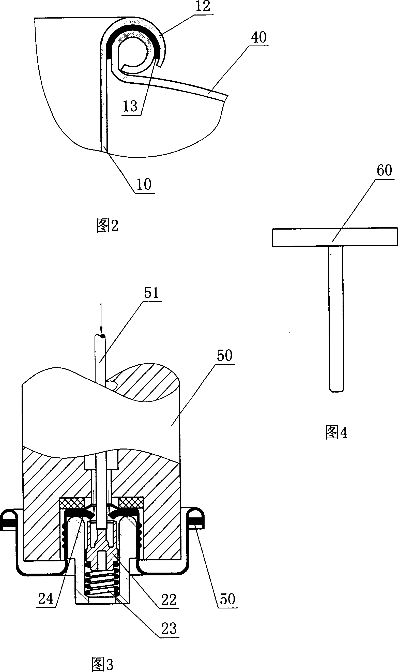
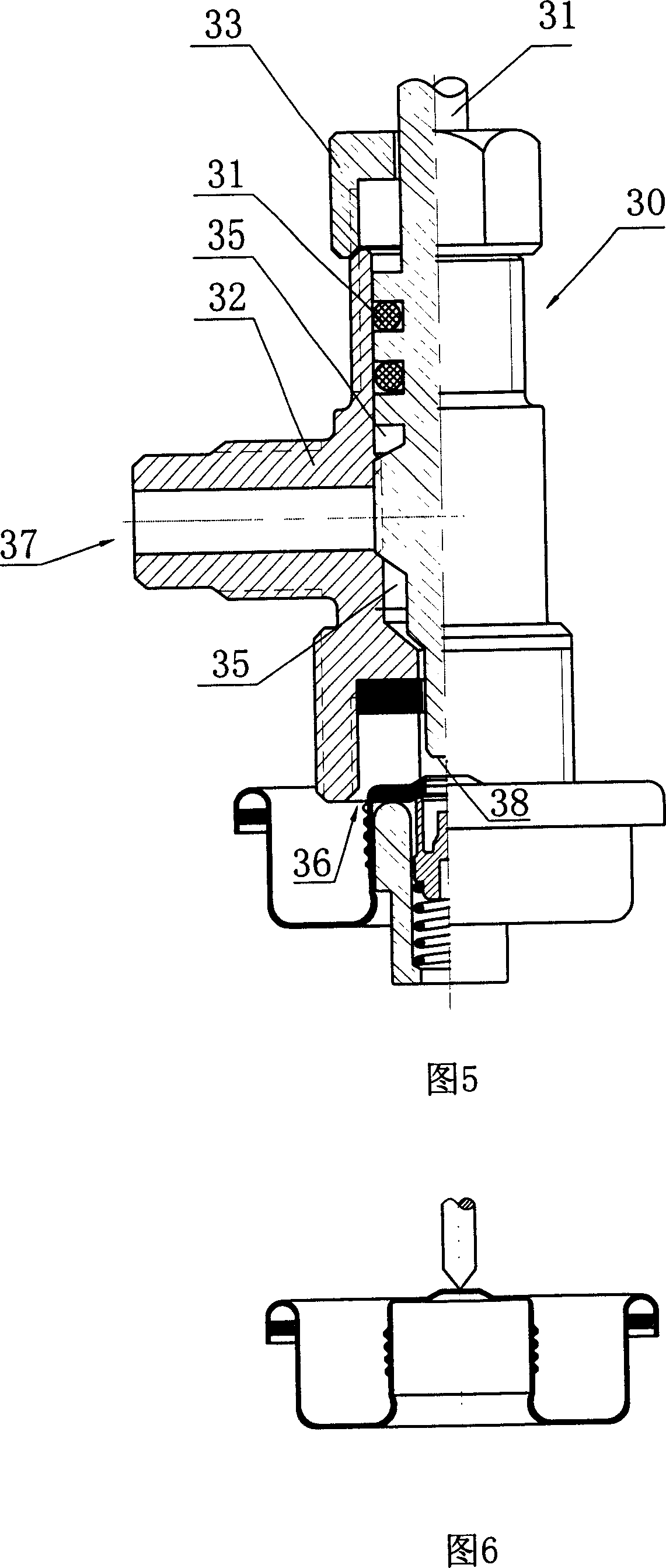
[0026] A washer 14 is placed in the cylindrical boss 11 at the center of the cover body 10 shown in FIG. 1 , and the temporary threaded aerosol valve is pressed into the boss 11 . This momentary threaded aerosol valve is made up of valve seat 21, valve core 22, and stage clip 23, stage clip 23 is placed in the inner hole 25 of valve seat, valve core 22 is connected on the free end of stage clip 23 upper side, can With the expansion and contraction of the compression spring 23, it moves axially in the inner hole 25 of the valve seat. The valve core 22 corresponds to and communicates with the top circular hole 15 of the boss 11 , and the valve seat 21 and the upper end surface of the valve core 22 are tightly pressed on the gasket 14 to be in sealing connection therewith.

[00...

Embodiment 2

[0038]In this embodiment, a 400 ml refrigerant tank is used to fill R134a. The concrete steps of the structure of the capping and the bottle opening key and the filling and discharging method of the refrigerant are the same as in Embodiment 1. Wherein, the gasket 14 and the sealing ring 13 used in the refrigerant tank are all made of solvent-resistant rubber.

Embodiment 3

[0040] This embodiment is filled with a 300 milliliter refrigerant tank? R12. The concrete steps of the structure of the capping and the bottle opening key and the filling and discharging method of the refrigerant are the same as in Embodiment 1. Wherein, the gasket 14 and the sealing ring 13 used in the refrigerant tank are all made of solvent-resistant rubber.


PUM


Abstract

The invention relates to a refrigerant tank with less than 1000ml. the procedure for the loading and discharging method of refrigerant is that a) inhalator valve with inch screw thread is set on the upper sealing cover of refrigerant tank; b) sealing cover is pressed to the tank, in which it is vacuum; c) refrigerant is loaded into the tank by the inhalator valve with inch screw thread on the sealing cover; d) residual air on the top of tank is discharged and product refrigerant tank is produced; e) refrigerant is discharged by inhalator valve with inch screw thread opened by the key. The sealing cover of refrigerant tank is that inhalator valve with inch screw thread is set in the cylinder convex platform at the center of cover, circular hole is set on the top of convex platform, sealing gasket is under the circular hole, the upper end face of inhalator valve with inch screw head is connected with sealing gasket hermetically. The merit is that it can be loaded under the ordinary temperature and pressure, investing cost is saved; refrigerant with water has less oxygen; residual refrigerant can be sealed in the tank; refrigerant tank can be loaded time after time, resource is saved and circumstance pollution is avoided by refrigerant.

Description

technical field [0001] The invention relates to a refrigerant tank, in particular to a method for filling and discharging a refrigerant tank with a capacity of less than 1000 milliliters and a sealing cover for the refrigerant tank. Background technique [0002] For many years, what the filling of small-package refrigerant tank below 1000 milliliters adopted is the method for capping disposable tinplate sealing cap 3 (accompanying drawing 5) after tank body is filled with refrigerant. When it is necessary to use the refrigerant therein, use the tip 2 on the special bottle opener to pierce the upper end of the cap to allow the refrigerant to flow out. [0003] After the cover of the above-mentioned refrigerant tank is pierced, the refrigerant must be fully charged into the air-conditioning system. If the system is full, the excess refrigerant has to be discharged into the atmosphere, and the tank cannot be reused. The refrigerant tank that is punctured in actual use often ha...

Claims


Application Information

Patent Timeline
IPC IPC(8): F17C5/02F17C7/04F17C13/06F17C13/04
Inventor 周飞
Owner 周飞
Why Eureka
Try Eureka