
Positioning unit for probe device

A technology for positioning parts and probes, which is applied to measuring devices, parts and instruments of electrical measuring instruments, etc., and can solve problems such as poor efficiency, fracture, and structural damage.

Active Publication Date: 2007-04-18
MICROELECTRONICS TECH INC
View PDF0 Cites 3 Cited by
  • Summary
  • Abstract
  • Description
  • Claims
  • Application Information

AI Technical Summary

Problems solved by technology

[0003] However, when assembling the above-mentioned probe device 80, since the positioning piece 84 is arranged on the lower base 82 first, and then each probe 90 passes through each opening 85 of the positioning piece 84, each probe 90 must be in the form of The oval body 94 passes through each opening 85, and the profile of the opening 85 is changed by force, so that the head 92 of each probe 90 can be arranged in the opening 85. The wall surfaces of 85 interfere with each other and cause structural damage, even fracture; and, when assembling each probe 90, each probe 90 must apply force to pass through each opening 85, so that the overall probe device 80 Assembly is time-consuming and inefficient

Method used


Image

  • Positioning unit for probe device
  • Positioning unit for probe device
  • Positioning unit for probe device

Examples


Embodiment Construction

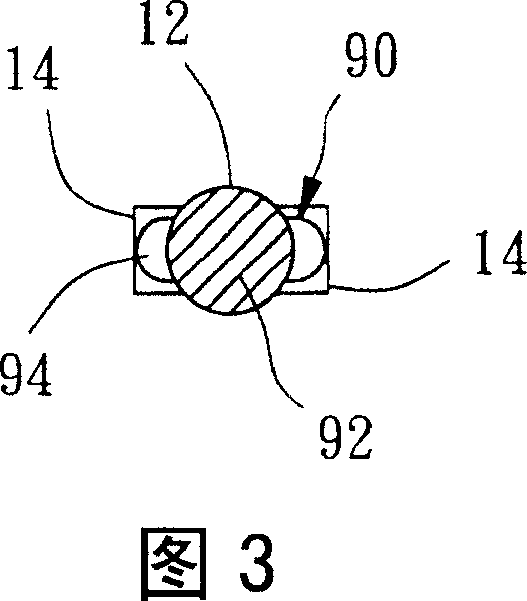
[0036] Please refer to Fig. 1, which is the positioning member 10 provided for the probe device according to the first preferred embodiment of the present invention, the positioning member 10 is a sheet made of polyimide (Polyimide) material, the positioning member 10 There are many through-shaped first openings 12, as shown in Figure 2 and Figure 3, each first opening 12 is roughly circular, and can accommodate the head 92 of the probe 90 as shown in Figure 12; Two second openings 14 are arranged around the opening 12, and each second opening 14 is roughly elongated. The width is slightly larger than the cross section of the body 94 of the probe 90 . The first opening 12 and the second opening 14 can be directly formed on the positioning member 10 by laser processing or mechanical processing such as stamping.

[0037] As shown in Figure 3, when each probe 90 was assembled in each first opening 12 of the locator 10, the oval body 94 of the probe 90 could pass through the two s...


PUM


Abstract

The invention relates to probe device locations which can conveniently assemble, locate each probe for the probe device without damaging its structure. The locations has many the first opening with throughout shape each of which at least one the second opening is set around. Each the second opening extends outward from each the fist opening wall surface.

Description

technical field [0001] The present invention relates to a probe device, in particular to a positioning element for the probe device. Background technique [0002] As shown in Figure 11, generally be used for the probe device 80 of testing semiconductor chip, comprise an upper base 81, lower base 82, and a plurality of probes 90, as shown in Figure 12, the head 92 of each probe 90 The cross-section is roughly circular, and the cross-section of the body 94 can be oval or square; in order to facilitate the assembly of each component of the probe device 80, the head 92 of each probe 90 is usually positioned on a positioning member 84 first, and the positioning Part 84 is made of a flexible sheet, and has a plurality of through-shaped openings 85. The shape of the openings 85 is similar to the cross-sectional shape of the head 92 of the probe 90, and the head 92 of each probe 90 is set in the positioning The opening 85 of the piece 84 makes the opening 85 constrain the probe 90 ...

Claims


Application Information

Patent Timeline
Patent Type & Authority Applications(China)
IPC IPC(8): G01R1/073G01R31/00G01R31/28
Inventor 林信宏尤嘉祥
Owner MICROELECTRONICS TECH INC
Learn More