Core for transformer
A transformer and iron core technology, applied in the direction of transformer/inductor magnetic core, inductor/transformer/magnet manufacturing, transformer/inductor parts, etc., to improve operating efficiency, prevent heat loss, and save costs
- Summary
- Abstract
- Description
- Claims
- Application Information
AI Technical Summary
Problems solved by technology
Method used
Image
Examples
Embodiment Construction
[0015] Embodiments of the present invention will be described below with reference to the drawings.
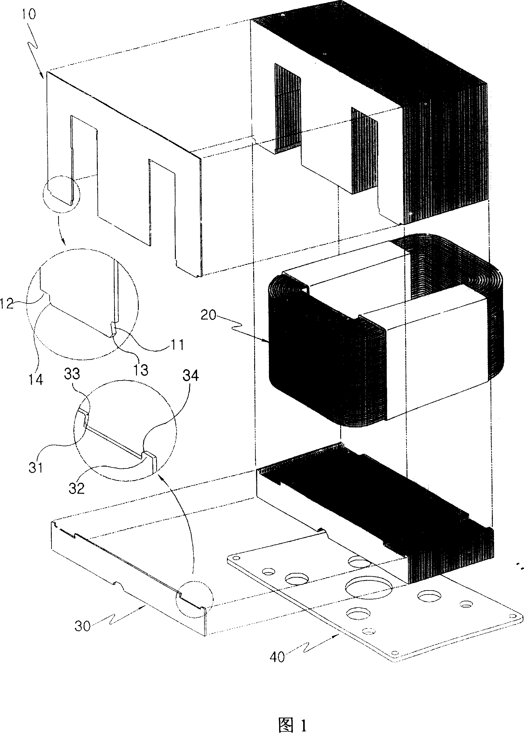
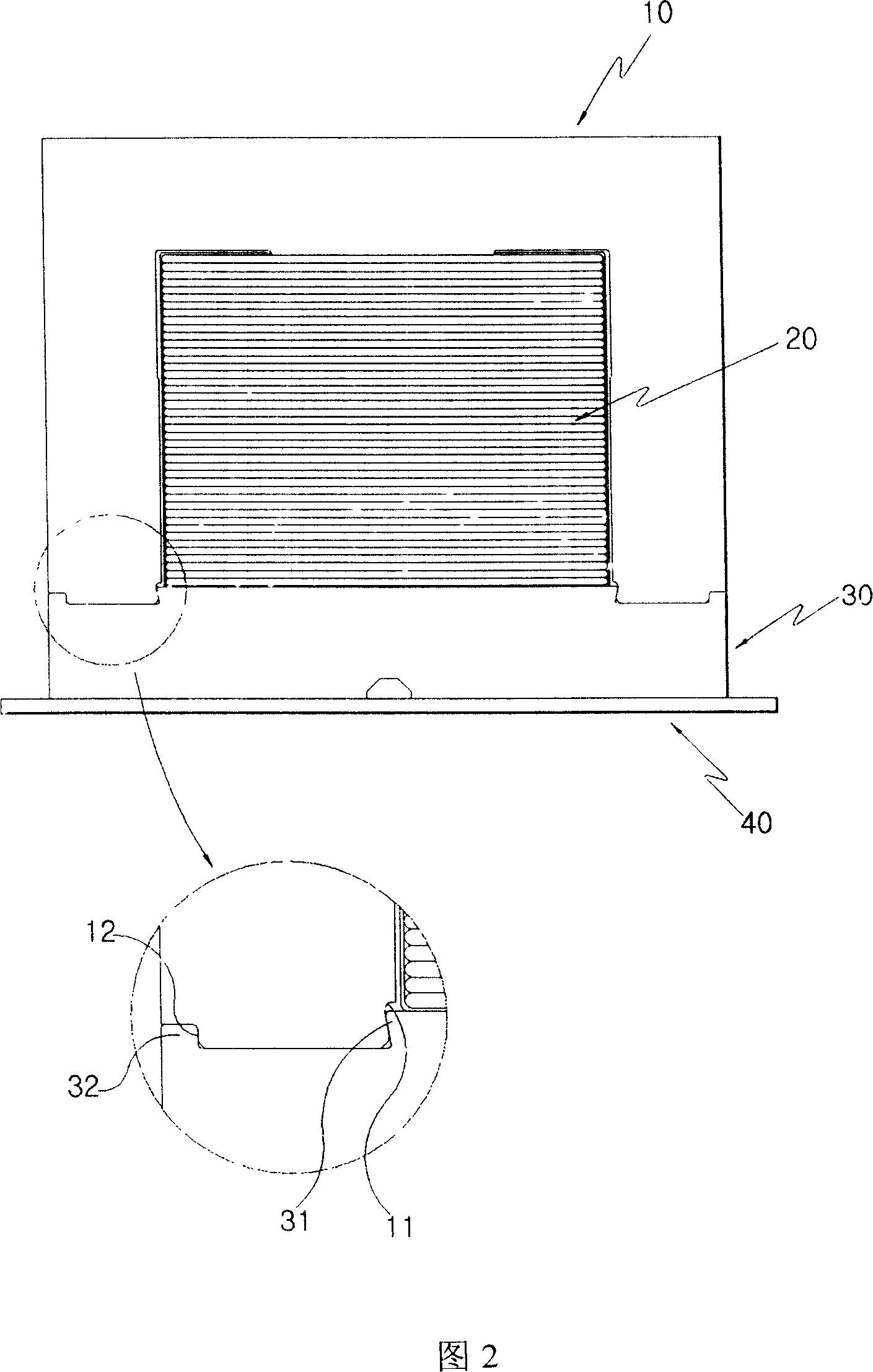
[0016] An iron core for a transformer according to an embodiment of the present invention is shown in FIG. 1 and FIG. 2 . It is constituted by inserting a winding coil 20 into an E-shaped iron core 10 and combining an I-shaped iron core 30 into the E-shaped iron core 10. . In addition, on the E-shaped iron core 10, two support grooves 11, 12 are respectively formed on the outer two ends of the contact portion with the I-shaped iron core 30, and two support grooves 11 and 12 are respectively formed on both sides of the I-shaped iron core 30. , 12 corresponding to the supporting protrusions 31,32. Therefore, the E-shaped iron core 10 and the I-shaped iron core 30 are formed by combining the support protrusions 31 , 32 with the support grooves 11 , 12 in a state where a plurality of them are evenly arranged. At this time, in order to prevent the support protrusions 31, 32 from ...
PUM
| Property | Measurement | Unit |
|---|---|---|
| length | aaaaa | aaaaa |
Abstract
Description
Claims
Application Information
 - Generate Ideas
- Intellectual Property
- Life Sciences
- Materials
- Tech Scout
- Unparalleled Data Quality
- Higher Quality Content
- 60% Fewer Hallucinations
Browse by: Latest US Patents, China's latest patents, Technical Efficacy Thesaurus, Application Domain, Technology Topic, Popular Technical Reports.
© 2025 PatSnap. All rights reserved.Legal|Privacy policy|Modern Slavery Act Transparency Statement|Sitemap|About US| Contact US: help@patsnap.com


